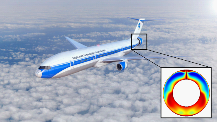
Recently, many new concepts for future emission-free aircraft have been presented. On closer inspection aircraft manufacturers are also relying on new integration concepts for the engines. The result is that engines suck the boundary layer from the aircraft fuselage. For the aircraft as a whole, this reduces drag, which potentially reduces fuel consumption. At the engine level, however, the disturbed inflow poses challenges to both aerodynamic operational behavior and structural dynamic design.
Boundary Layer Ingestion – A trend with many implications
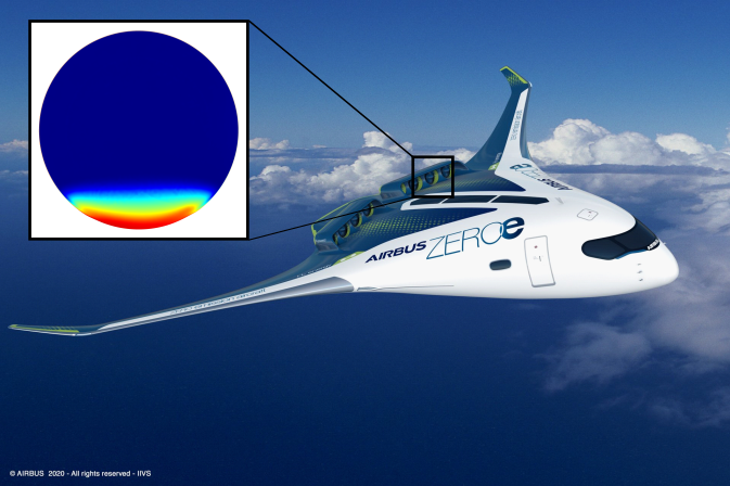
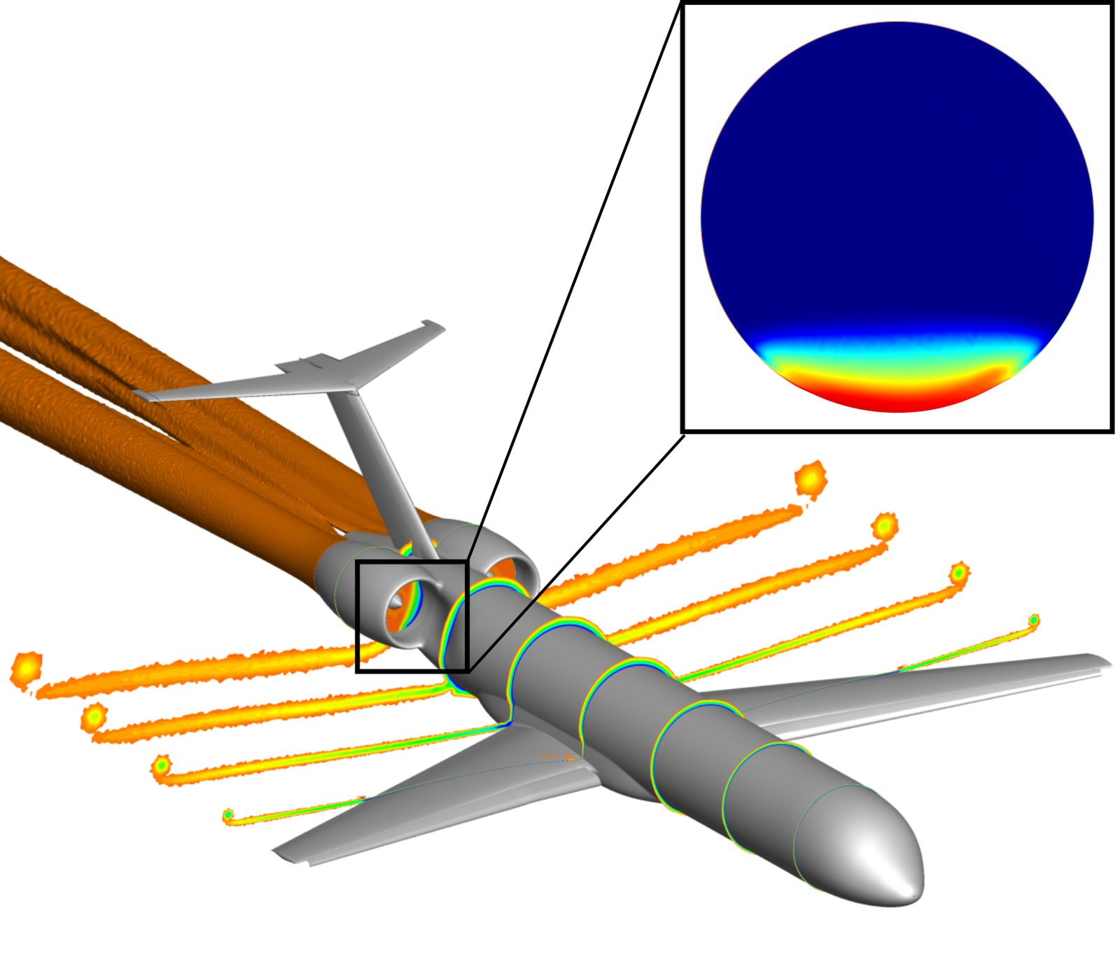
Figure 2: DLR-TuLam Konfiguration mit eingebetten Triebwerken
In the development of future aircraft concepts, propulsion systems with boundary layer ingestion (BLI) have a valuable potential for multiple reasons. For example, improved integration of the engines into the fuselage reduces the aircraft's drag, which in turn reduces the propulsion power required. For the engine fan, sucked-in boundary layers and other flow disturbances affect many of its sub-elements. Reduced aerodynamic efficiency, increased blade vibrations and the excitation of additional noise sources have to be expected. In order to comprehensively evaluate these effects on the various disciplines of fan design, the DLR project AGATA3s will deepen the understanding of the physical mechanisms. For the investigation, the DLR’s commercial aircraft concept TuLam was set as a basis and the CRISPMult-Fan was integrated into the aircraft’s tail. The blades of the CRISPMulti-Fan are made of carbon fiber reinforced plastic (CFRP), which makes it more susceptible to vibrations due to its lightweight construction.
External aerodynamic vibration excitations for turbomachinery
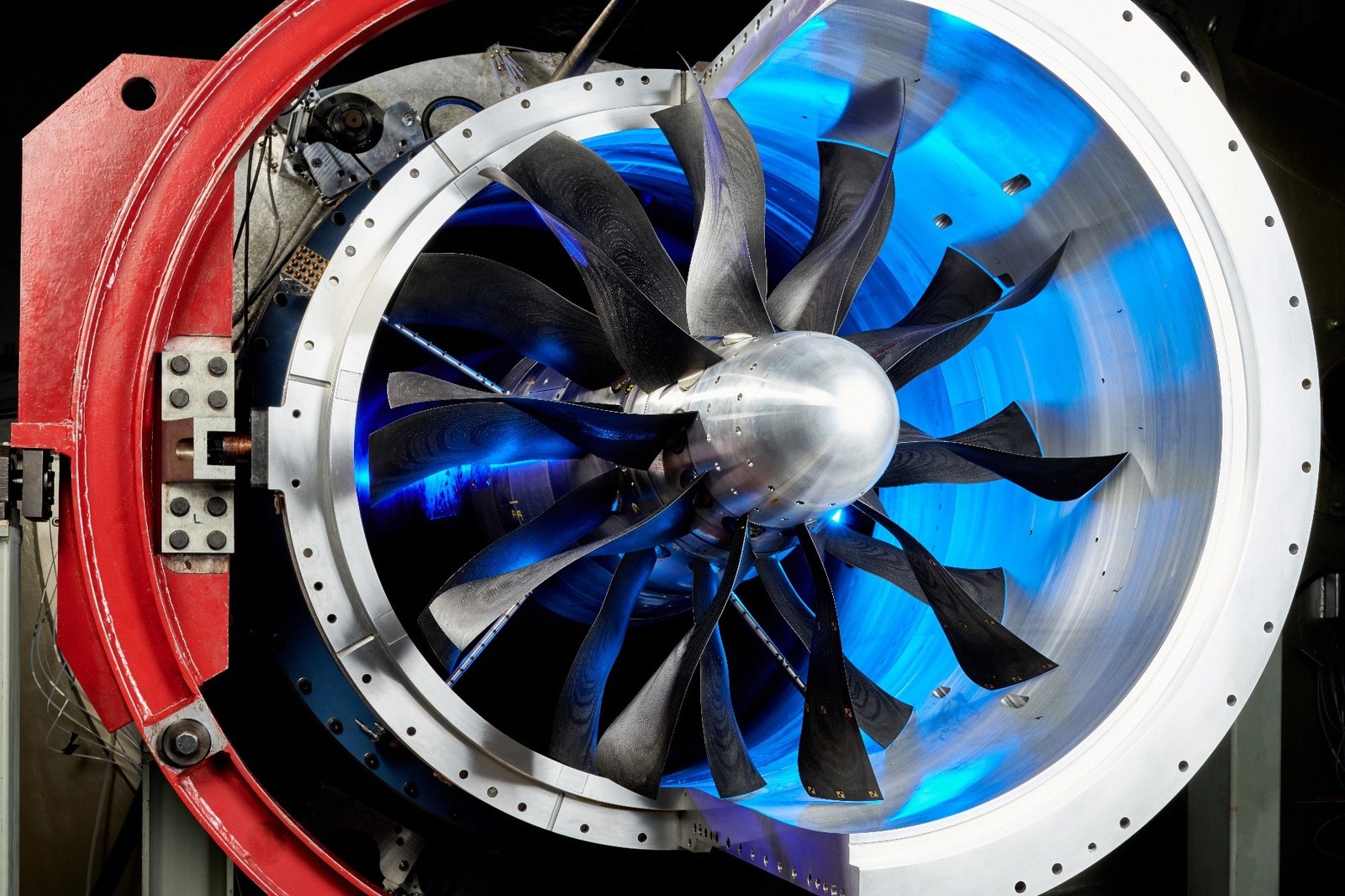
Figure 3: CRISPmulti-Rotor im M2V-Prüfstand am DLR-Standort in Köln
Aerodynamic phenomena induce engine blade vibrations. In contrast to the so-called flutter, which is a self-excited vibration, the causes of external aerodynamic excitation can be diverse. Examples are the stator or rotor wake, a nonuniform inflow (e.g. due to cross flow) or, as in this case, the deliberate ingestion of a boundary layer (BLI). Excitation typically occurs at a multiple of the rotational frequency. This multiple is called the engine order (EO). The excitation modes differ not only in their excitation order, but also in their disturbance intensity. A broadband excitation by a BLI, in terms of both the excitation order and the excited vibration modes, requires an in-depth structural evaluation of the response behavior. The passage through a periodically changing pressure field in the circumferential direction is one of the elementary design criteria to assess the dynamic loading of the blades. Since the excitation permanently affects the structure during operations, failure criteria have to be met and service life aspects need to be estimated.
Engine blades might vibrate as well
Figure 4: Variation of the pressure coefficient distribution when the blade is passing through the inflow distortion
As a simplified evaluation method of externally excited blade vibrations, the so-called energy method is used in the turbomachinery sector. It assumes that in resonance, if an excitation frequency is identical to an eigenfrequency, the relevant eigenmode and excitation order dominate and it is therefore sufficient to restrict the evaluation to these. This leads to significantly reduced simulation efforts. However, for complex excitation mechanisms, such as those present in a BLI fan, this simplified approach is no longer sufficient. In this case, modal superposition is applied, where both the individual responses of several responding eigenmodes and the structural response to different excitation orders can be superimposed.
Aerodynamic excitation mechanisms
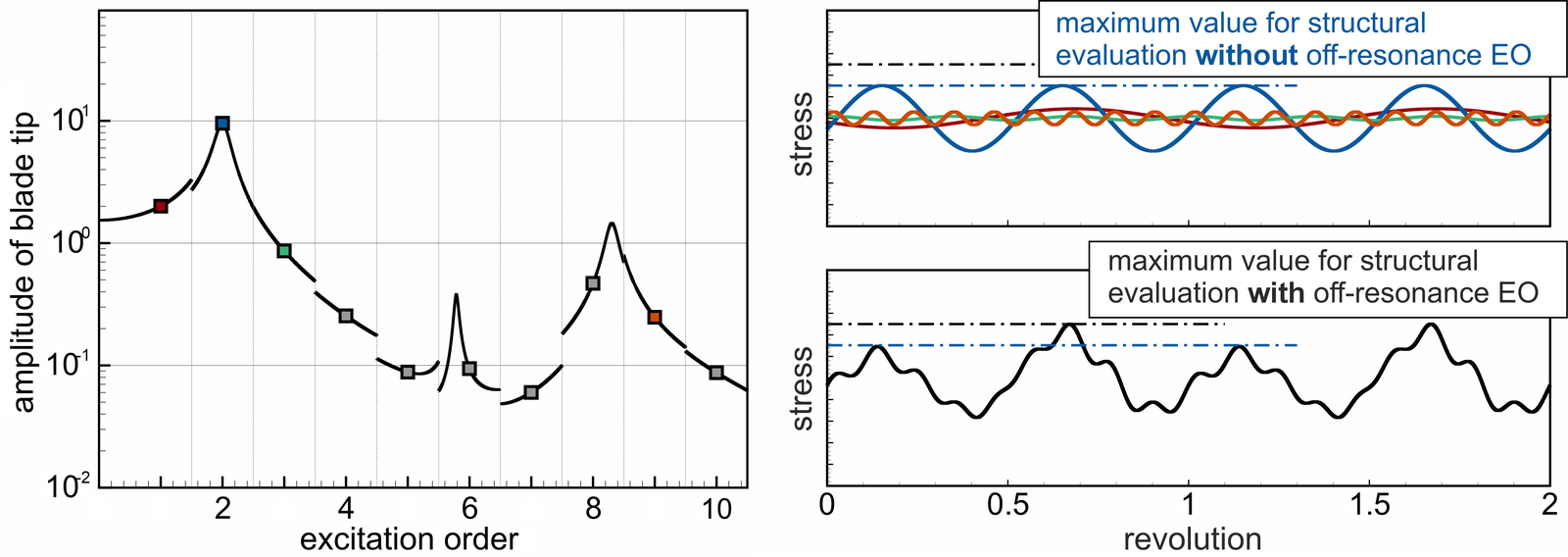
Due to the boundary conditions prescribed by the excitation frequencies and structural properties (especially the eigenfrequencies), a wide variety of operating conditions have to be evaluated. This number is significantly increased if the excitation of an inflow distortion has to be taken into account. The resulting variation of the pressure coefficient distribution when the blade is passing through the inflow distortion is shown in Figure 4. Thus, in addition to safe operations at design speed, the safe passage through of many resonance points have to be guaranteed as well. Figure 5 shows the vibration amplitude of the blade tip calculated for a defined disturbance, a specific operating point and for the first ten excitation orders (excitation frequencies marked with symbols). With the simplified evaluation procedure, only the vibration response to the second excitation order can be assessed (shown on the left-hand side with a blue symbol, on the right-hand side as a blue line). For an accurate structural evaluation, the sum of the responses to several excitation orders is essential (shown in black on the right-hand side), otherwise the response behavior would be clearly underestimated.
Figure 5: Calculated vibration response for a defined disturbance and operating point
Left-hand side: Vibration amplitude of the blade tip, excitation frequencies marked with symbols, right-hand side: resulting stress for individual excitation orders (top) and the sum of the excitation orders (bottom).
Due to the expertise and process chains developed at the Institute of Aeroelasticity, it is now possible to perform an accurate evaluation for a wide variety of disturbance patterns and thus to select and plan suitable disturbance profiles for the experiments. This ensures that these experiments can be carried out safely. The knowledge gained from the experiments can then be used to draw conclusions for future anchor designs for BLI applications in order to make them safe and efficient.
Eichner, Franziska and Belz, Joachim and Winkelmann, Peter and Schnell, Rainer and Lengyel, Timea (2019) Prediction of Aerodynamically Induced Fan Blade Vibration due to Boundary Layer Ingestion. In: 13th European Turbomachinery Conference on Turbomachinery Fluid Dynamics and Thermodynamics, ETC 2019. ETC 2019 - 13th European Turbomachinery Conference, 08.-12. Apr. 2019, Lausanne, Schweiz
Author:
Franziska Eichner, DLR-Institute of Aeroelasticity, Department: Aeroelastic Experiments


