
GETEX
German Technology Experiment on ETS-VII
From April 19-21, 1999 DLR’s tele-robotic and programming system was used to control the robot arm on the Japanese ETS-VII satellite. The main goals of the German ETS-VII Technology Experiments (GETEX) were to verify our tele-robotic ground control station for remote control of a free-floating robot, in particular to perform a peg-in-hole experiment, using VR methods and the "vision&force" control scheme, by closing sensor control loops directly on-board (force) and via the ground track (vision), thus proving our sensor-based autonomy features, to conduct experiments with relevance to the behavior of the ETS-VII in free motion mode and thus to verify the existing 6 DoF dynamic models for the interaction between a robot and its free-flying carrier satellite.
All the experiments were shown live at the Internet via Video transmission and a VRML simulation which showed the current robot and satellite status in an impressive way.
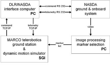
To check and test our interfaces as well as our MARCO control system within the ETS-VII scenario, an on-line simulator was developed, which emulated the remotely operated robot, its command interfaces and its environment. The simulator is able to emulate all different modes, the timing, the environmental interactions, and the prediction of the satellite’s attitude while moving the robot arm. This kind of simulation has turned out to be very useful for proofing software correctness while interacting with the tele-robot.

Peg-in-hole experiment, using VR methods and the „vision&force“ control scheme
After teaching the desired peg-in-hole task in the VR environment, i.e. pick TBTL (TaskBoard TooL) and placing it into HOLE A, the execution was started and performed fully automatically on-board:

To get the TBTL, we first carried out a visual servoing task, using some marker features in the video image to control the tool center point (TCP) of the robot autonomously into the desired sensor-related pose. For that reason we developed an approach, which doesn’t need any calibration. The control law may be written as
vc = a C (s-s*)
where (s-s*) is the vector-valued deviation between the current and the nominal sensory pattern indicating the displacement of the current robot pose x from the nominal pose x*. vc is the velocity command, a represents a scalar dynamic expression, at least a real constant, determining the closed control loop behavior, and C represents a projection operator used for mapping the sensor space into the (cartesian) control space. C is determined by neural network learning or using analytical methods.

We applied the analytical method for the determination of C, which is represented by the pseudoinverse of the Jacobian matrix of the m deviations in the sensor space w.r.t. the n deviations in the control space. For that we moved the robot’s TCP a little bit around in all n=6 degree of freedom, recorded the corresponding sensor values and generated the Jacobian out of the resulting difference quotients.

We performed the experimental determination of C in our simulation environment as well as in the real one. The result was nearly the same, due to the accuracy of our camera simulation. The camera parameters have been estimated by means of an in-house developed camera calibration tool.

For the control we used the TaskBoard marker features, which were originally available to tele-operate the TCP into the right position. The goal was to find the markers in the life video image and to generate the appropriate straight path command in order to move the robot into the desired (sensor-defined) target pose. To verify the vision-based sensor control loop, the TCP was moved intentionally into a position different from the optimal target pose (a few centimeters in all translational directions and about 20 degrees in z-rotation).
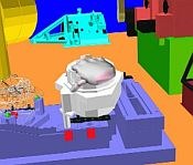
After 3 cycles (with a = 1), the target pose was reached. To extract the markers from the video image a blob-finding algorithm was used. Because this algorithm delivered more „markers“ as desired, e.g. due to bad illumination conditions, the markers were interactively selected and the resulting control command was verified before sending it to the real robot. The figure above shows the simulated(_) and the real(X) markers, with the interactive selection frame.
The differences between the _ and X markers result from a different TCP pose, to show the two representations. If real and simulated TCP are the in the same pose, the real and simulated markers have nearly the same 2D-coordinates.
The simulated and measured pixel coordinates are shown in the table below. They differ only in the subpixel domain.
X1 | Y1 | X3 | Y3 | X4 | Y4 | |
|---|---|---|---|---|---|---|
real | 273.8 | 240.1 | 365.7 | 240.3 | 411.6 | 240.3 |
0 | 7 | 0 | 5 | 0 | 7 | |
sim | 273.9 | 240.3 | 365.8 | 240.5 | 411.7 | 240.5 |
4 | 8 | 1 | 6 | 1 | 9 |
Table 1 - measured and simulated pixel coordinates
Dynamic Motion Experiments
A major part of the GETEX experiment time was allocated to the so-called “Dynamic Motion Experiments”, consisting of a series of maneuvers carried out by the manipulator while the attitude control system of ETS-VII was switched off.
For space robotic systems that are neither position nor attitude controlled the angular momentum conservation law leads to a rotation of the spacecraft by an amount that results from the mass and inertia properties of the manipulator links and the spacecraft. It is generally assumed that no external forces act on such free-floating robots.
As long as the tasks performed with the robot are described in robot-fixed coordinates, the fact that the satellite position remains uncontrolled has no influence. If, however, the task is described with respect to an orbit-fixed co-ordinate system, as it would be the case for example for the capturing of another defective satellite, the robots satellite motion has to be taken into account (see Figures). The equations relating the TCP motion to the manipulator joint motion, which for robots with an inertially fixed base are purely kinematic equations, therefore become dependent on dynamic parameters in the case of free-floating space robots due to the fact that the momentum equations are used to describe the satellite motion.

This influences the path planning methods which have to be applied. On one hand, singularities, that are joint configurations in which the robot is not controllable in Cartesian coordinates, are no longer a function of the robot kinematics only, but become dependent on the dynamic properties of the robot, too. Therefore, iterative methods based on the direct kinematic equations have to be used instead of the inverse kinematics equations. Moreover, the angular momentum equation makes the system non-holonomic, which means that the satellite orientation is not a function of the current joint configuration only, but also a function of the chosen path.
Two different paths starting at the same initial configuration of the robot, and leading to the same final configuration, will therefore result in different amounts of satellite rotation – and thus in different final inertial TCP positions, too. As a consequence, non-holonomy offers the possibility to do a re-orientation of the satellite using manipulator motion only, by simply carrying out a closed-loop maneuver in joint space.
Whatever path planning method is applied to free-floating robots is necessarily highly model-based. The parameters of the dynamic model have therefore to be known quite well. While this poses no problem for the geometric parameters and for the mass and inertia of the manipulator, the mass and the inertia of the spacecraft are subject to important changes during the lifetime of a servicing satellite. This is especially the case if the spacecraft is performing capturing or rendezvous/docking like operations.
One goal of the GETEX experiments has therefore been to identify the mass properties of the satellite after one year and a half of activity in orbit. Further objectives were the verification of the dynamic models and to obtain some insight into the nature and importance of the disturbances acting on a robotic satellite on low Earth orbit. Additionally, the mission aimed at gathering data for the future design of controllers that combine the manipulator motion control with the satellite attitude control. To meet all these objectives, a variety of different maneuvers were executed by the manipulator while the attitude control system of ETS-VII was switched off.
Experiments
The following maneuvers of the manipulator on-board the ETS-VII satellite were performed:
- point-to-point maneuvers
- maneuvers to determine a variation of the attitude of the satellite
- optimized maneuvers to minimize satellite base motion or manipulator joint motion (minimum energy maneuver)
During the first half of the experiments, the satellite attitude control system was switched to "free-floating mode", allowing a free-floating condition of the system within an attitude range of a few degrees. Since during normal operation mode the satellite was given a nominal angular rate equal to the orbital rate, such that it would always point in the same direction towards Earth, also during the free-floating motion experiments the angular rate of the satellite was unaltered, as the satellite kept rotating due to its inertia.
The experiments were performed in five slots of twenty minutes, where the first ten minutes were in free-floating mode and the last ten minutes were with the attitude control system (AOCS) switched on.
In each slot, the following procedure was performed:
- unloading of the momentum wheels using attitude control thrusters
- reduce the residual angular velocity of the satellite to a lower value by spinning up again the momentum wheels
- AOCS switched to free-motion mode
- perform maneuvers
- AOCS switched to momentum wheel motion control mode
- repeat maneuvers.
Results of the experiments
The following discussion will refer to the first representative slot of experiments, for which the maneuvers shown in figure 6 were performed in succession. The figure shows the end-effector motion (continuous line) simulated with an ideal free-floating model (free of external actions). Note that the first is a point-to-point maneuver while the second is a closed-loop maneuver.
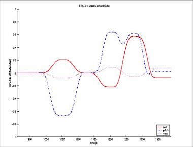
Real end-effector motion with respect to the satellite was found to coincide with the simulated motion. The satellite attitude motion during the free-floating condition was found to differ from the simulated motion, as shown in figures 7a and b. The figures show the Euler parameters describing the satellite attitude relative to the orbital frame in function of time.

Of interest is also the angular momentum of the reaction wheels which is shown in figure 8 for all the duration of the first slot. The figure shows that the momentum during the free-floating condition time of the experiment (910-1360 seconds) had some small non zero value, due to the second phase in the above mentioned sequence.

Analysis of the experimental results
Figure 7a shows how, by comparing the initial and final values of the attitude parameters, the closed-loop manoeuvre gives rise to a small variation of the satellite attitude.

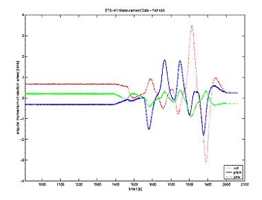
Figure 7b however, shows a substantial drift of the satellite superimposed on the motion induced by the manipulator motion, shown in figure 7a. This drift has been found to depend mainly on the following factors:
- the gravity gradient acting on the satellite
- the coupling between the residual angular momentum of the momentum wheels and the orbital angular velocity of the satellite
- the residual angular velocity of the satellite with respect to the orbital frame of reference at the beginning of the experiment.
Other factors, such as the interaction of the satellite magnetic dipole with the Earth magnetic field, solar pressure and aerodynamic drag were taken to be second order effects. The aerodynamic drag was in fact measured by NASDA and was found to be small in size. Finally, moving parts on the satellite, such as the solar panels and the communications antenna, were found to give a small disturbance to the motion of the satellite about the pitch axis, after simulation.
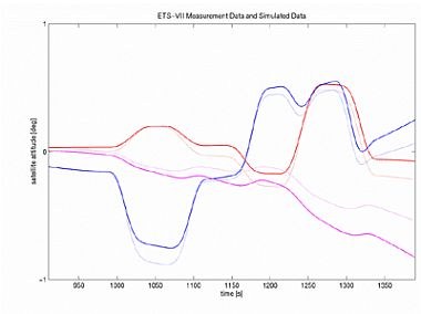
The simulated data of the updated multibody model, which accounts for the above points, is shown in figure 9 (dotted lines), in comparison to the measured data (continuous lines). It is clear from this figure that there is still a discrepancy between the two sets of data. This is thought to be due to an approximate value of the mass and inertia of the simulated model with respect to reality, as the results were found to be very sensitive to variations of the simulated values. In fact, although the properties of the manipulator arm are known from measurement prior to the launch, those of the satellite are only known approximately due to the fuel consumption during the lifetime of the satellite. An estimate of the initial satellite inertia was also necessary due to the fact that the mass and inertia data was only known at launch for the complete system with the manipulator in the stowed configuration.
A parameter identification problem can be defined and solved such that these quantities can be determined. Note that the unknown quantities are the mass and inertia of the satellite and the position of the center of mass of the multibody system. This problem, if solved, will give rise to the possible development of a new method for measuring mass and inertia properties of a space robot in orbit.
The experimental results have also shown that the modeling of the external torque acting on the satellite (standard disturbances which act on orbiting space systems) have to be included in the overall model of the system, if maneuvers of the manipulator need to be referenced to inertial space, or to another spacecraft. In developing the model used for this experiment, in fact, it was assumed that such disturbances were negligible for the purpose of the experiment. This is because the duration of the maneuvers was thought to be short enough to neglect any external action on the satellite.
The unexpected drift of the satellite in time resulted in a partial failure of the second maneuvers listed above, since it was not possible to determine the rotation of the satellite with respect to inertial space during the experiment. However, despite this unexpected behavior of the system, all maneuvers were performed while satisfying the limitations on satellite attitude variations of 1 degree about each axis to an acceptable degree.
As a conclusion, the GETEX dynamic motion experiment has been useful in validating the model of the ETS-VII satellite-manipulator system for maneuvers referenced in the satellite’s frame, realizing that it is necessary to account for the external disturbances acting on a spacecraft in low Earth orbit for a correct modeling of the maneuvers referenced in the fixed inertial frame, and developing a model for the external disturbances to be validated with the experimental data.