
Steer-by-wire Joystick

To fit the demands of a steer-by–wire system some changes had to be applied to the mechanics and electronics of the DLR force feedback joystick.
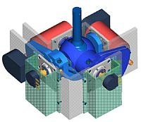
Mechanics
The motor-gear combination was changed to achieve forces up to 20N, the cardanic joint and the lever of the grip handle was designed to resist higher mechanical stress. For fail-safe behaviour at any drive or electronic failure some leg springs were added at each joystick axes to set back the handle in the initial position while not gripped.
The dimensions of the joystick case were adapted to fit in the arm-rest of a car seat.
Electronics
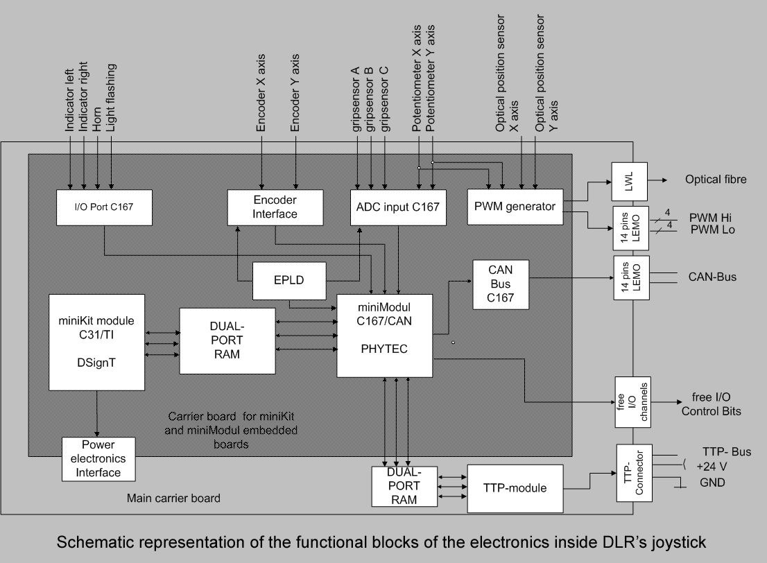
The functions needed in the steer-by-wire application could be implemented by using embedded modules. Onboard of a backplane system we used 2 credit card embedded modules: the C31 Texas Instruments module from DSignT GmbH for the force control and the C167 Siemens module from Phytec AG for interfacing the sensors and the bus communication (CAN, PWM differential Bus and TTP protocol). The data exchange between the C167, C31 DSP Controller and the TTP ‘piggy-back’ module is implemented over two asynchronous dual port RAM chips. For more information see also the block diagram of the DLR joystick electronics.
Schematic representation of the functional blocks of the electronics inside the DLR’s force feedback joystick: