
ESS
The ESS (Experimental Servicing Satellite) – Study and Lab Demonstrator
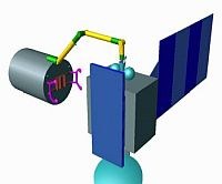
Immediately after ROTEX, we started to build up laboratory experiments for studying the dynamical behaviour and the rendezvous and docking capabilities of a free-flying servicing satellite, consisting of a robot arm mounted on a conventional chaser. A free-flying tele-robot ESS (Experimental Servicing Satellite) was supposed to approach, inspect, and repair a malfunctioning satellite. We emphasise that the movements of a robot arm, mounted on the body of the servicing satellite, cause feedback to the carrier system, which is non-negligible and might cause collision with the target satellite. Therefore the effects of the manipulator’s motion onto the carrier satellite have to be simulated, interpreted, and perhaps corrected on-ground. We had to consider two satellite configurations, expressed by their kinematic chains:
- ESS & mounted manipulator,
- ESS & mounted manipulator & docked target satellite.
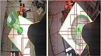
The manipulator of ESS, equipped with a capturing tool, must follow the residual movements of a selected object on the target (e.g. the main thruster) by means of an image processing system whose data are passed through an extended Kalman filtering process.
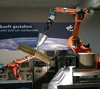
To simulate the dynamic behavior of the chaser during robot motions, we have arranged two KUKA robots as shown below. Robot B is used to carry out the capturing task, Robot A emulates the entire dynamic relation between the chaser and the target satellite, where the dynamic coupling with the AOCS is included.


After capturing the target satellite, the ensemble is stabilised and reoriented. To free the manipulator for servicing activities and to provide a stiff mechanical coupling, the target satellite is grasped by means of a docking mechanism.
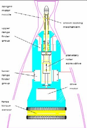
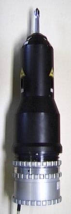
An interface to the simulation of the AOCS (Attitude and Orientation Control System) emulated the behaviour of the entire ESS under space conditions. A special, in-house-developed capture tool, containing 6 laser range finders, a wrist-mounted force-torque sensor, and a stereo camera pair, allowed, in combination with the dynamics behaviour prediction, the fully autonomous servoing, insertion, and capturing of the apogee motor nozzle, which is typical for any geostationary satellite. We simulated the visual servoing phase in the lab by the above-drafted two-robot system. One robot carries a satellite mockup with an original-sized apogee nozzle, performs a typical tumbling motion of a rigid body under zero gravity, and superimposes the computed dynamic interactions of the service robot with its (possibly) free-floating base. Thus in the lab the service robot (a second robot) is inertially fixed and tracks the satellite in order to capture it by inserting the capture tool into the apogee motor. The approach of the target satellite is controlled by real-time, model-based machine vision. Once contact between capture tool and apogee motor has been established, force/torque-sensing takes over. In both phases all Cartesian degrees of freedom are being controlled.