
Mechatronic design of the LWR III
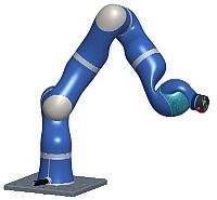
The LWR III is a light-weight, flexible, revolute joint robot, which is due to its sensoric equipment fit for robot-human interaction. The robots size, power and manipulation capabilities are fairly similar to that of a human arm. The robot can be connected to any gripper or tool by a standard robot interface flange, which can also be operated over internal supply lines.

Kinematics
The LWR III has 7 revolute joints for good manipulation capabilities in a changing workspace with unpredictable obstacles. As the arm is dedicated to operate the DLR artificial Hand II for research on human haptics, its kinematics is similar to that of a human arm. In this context the first roll-pitch-roll combination can be seen as shoulder and upper arm, followed by pitch-roll for the elbow and forearm and concluded by a pitch-pitch combination with intersecting axes (kardanic) as a wrist. For applications using tools or grippers mainly, an alternative configuration as pitch-roll wrist is provided in the mechanical design.
Joint | Joint angle range |
|---|---|
Joint 1 | +/-170° |
Joint 2 | +/-120° |
Joint 3 | +/-170° |
Joint 4 | +/-120° |
Joint 5 | +/-170° |
Joint 6 | +80°/-45° |
Joint 7 | +60°/-30° |
LWR III Robot Joints
The robot is made up of intelligent joint units with integrated electronics, which are connected by supply lines, an emergency loop circuit and an optical SERCOS bus for data transfer. The robot structure consists of different structure links made of carbon fibre composite.
Each joint is equipped with a motor position sensor, a link side position sensor and a joint torque sensor. Thus the robot can be operated position, velocity and torque controlled. Especially the joint torque sensor plays a key role in this context, being used for:
- Active vibration damping: The torque sensor measures the vibrations caused by the elasticity on the link side and allows active vibration suppression with a full state feedback controller.
- Actively adjustable compliance: The compliance of the arm can be adjusted by measuring the external torques acting on the robot and by using these measurements within an impedance controller. In this way, the robot can compensate for uncertainties in the environment perception and reduce the contact or impact forces. For example the robot can behave rather soft in directions with high uncertainty, while being at the same time stiff in directions where high precision is required.
- Collision detection: Based on the torque sensor information and on an accurate robot model, collisions of the arm with the environment can be detected along the entire robot structure. The robot can then react by switching to the low impedance mode.
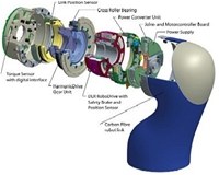
Joint units
The joint units consist of
- a DLR brushless RoboDrive DC Motor with integrated power converter and electromagnetic emergency brake
- a gear unit from Harmonic Drive
- a torque sensor on the output side of the gear
- position sensors on motor and output side of the gear
- an electronics stack consisting of power supply, joint and motion control DSPs and power converter for complete state feedback control of the joint
- the joint bearing consisting of a thin section cross roller bearing
Motors
For operating the LWR a brushless DC motor is used, which was specially developed for this task by DLR. All the parameters forming these motors have been optimized for the controlled operation in a robot and for light weight. As the required torque decreases over the length of the arm, three different types of the motor design are used (85, 70 and 50 mm Type).
Gear units
In the LWR III different HarmonicDrive gear units are used due to their high gear ratio and torque vs. weight. The gear ratio is 1:160 (Joint 5: 1:100), which allows torque output of 200 (165), 100 (70) and 40 (30) Nm maximum (measuring range) and up to 1.9 rad/sec angular velocity for the joint.

Torque sensor
Each joint in the LWR is equipped with a torque sensor on its output side between gear unit and structure. The torque sensor measures with a full bridge of strain gauges. The measuring range of the different joints is (+/-) 165, 70 and 30 Nm for axes 1/2, 3-5 and 6/7.
Positions sensors
Each joint contains two different position sensors. One incremental sensor with high resolution on the motor side, for motor commutation and joint control, and another, absolute sensor on the output side of the gear for joint angle reference.
Power Supply unit
Each joint has its own power supply unit. The galvanically isolated supply voltages are generated from a 48V-DC-Input. The supply unit powers the controller board, the power converter and all sensors. An overall of six voltages are generated.
Joint- and Motorcontroller Board
The controller board contains two DSPs. The joint controller runs with 330µs cycle time on a TMS320VC33 floating point DSP from TI. This DSP is responsible for the communication with the robot controller over a SERCOS bus, memorize and calibration of sensor data, and the calculation of current commands for the motor controller via a dual port ram. The motor controller, a DSP56F807 from Freescale/Motorola, calculates the motor position and speed with 25us cycle time and measures temperatures, motor currents and hall signals.
Power Converter
The power converter has been developed for three phase motors. Two phase currents and the bridge voltage are measured galvanically isolated.
Besides the motor the safety brake is controlled via the power converter board.
Parameter | Value |
|---|---|
Supply voltage | 48 V |
Maximum motorcurrent | 15 A |
Switching frequency | 40kHz |
External components | safety brake |
Current measurement | 2 motor phase currents (galvanically isolated), brake current |
Voltage measurement | Bridge voltage (galvanically isolated) |
Structure
The robot link structure is an exoskeleton made of carbon fibre composite. The different links consist of single direction carbon fibre rowings, which are sewed onto a carrier fabric. These preforms are put into a negative, soaked with epoxy resin and finally pressed to eliminate surplus resin to reduce weight. With this technique light and stable free form links can be produced, in which the carrying fibres can be placed optimally to take the expected loads.