
LWR I (1991–1996)


The LBR I was the first lightweight robot of the Institute of Robotics and Mechatronics. Due to its low weight and the torque sensors integrated in the joints, this robot allowed to investigate future application possibilities of cobots in the field of assembly and human-robot collaboration.
The LBR I was completed in 1995.
Technical specifications
Total Weight | 14.5 kg |
Max. Payload | 7 kg |
Max. Joint Speed | 120 °/s |
Axes | 7 (R-P-R-P-R-P-R) |
Total Length | 1338 mm |
Motors | Stepping Motor Escap |
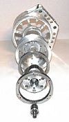
Gears | DLR Planetary Gear |
Sensors (each joint) | 1 Incremental Position Sensor, 1 Torque Sensor |
Brakes | Self-locking Gear |
Power Supply | 50V 20 kHz AC-Bus |
Control | Position-, Torque-, Impedance Control |
Electronics | Control Cycles: Current 40 kHz, Joint 2 kHz, Cartesian 1 kHz |
System description
At the Institute of Robotics and Mechatronics the first telemanipulated robot system used in space was developed for the space robot experiment ROTEX of the D2 mission (STS-55 from 1993-04-26 to 1993-05-06) in cooperation with Dornier (1986-1993). It demonstrated in an impressive manner that it was possible to control a space robotic system from Earth. On-board autonomy was used to compensate for the occurring orbital delays of up to seven seconds. This autonomy was achieved using the multisensory ROTEX gripper. The robotic arm used in the mission was not able to carry its own weight on Earth.
For the training of the astronauts, however, a lightweight and flexible robot was needed: The idea for the first lightweight robot (LBR I) was born. In the first design, the arm had 6 joints and was similar to the flight model of the robot in the ROTEX experiment. Later, a seventh rotational joint was added between axis 2 and 3, providing the robot with a redundant degree of freedom. The kinematics of the robot was similar to that of the human arm, each joint was equipped with a torque sensor, all electronics were integrated into the robot arm, and weight was reduced wherever possible.
The LBR I already had many of the features of the later DLR lightweight robots, which were combined in one robot arm for the first time:
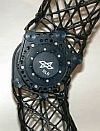
- Lightweight design
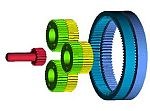
The joints were made of aluminum except for the transmission gears. The structural elements were wound lattice structures made of carbon fiber. - Adapted drive technology
In-house developed, high-reduction and compact planetary gears were combined with extremely small stepper motors with high dynamics and low weight. - Decentralized electronics
Each axis had integrated into the structure a local power section based on MOSFETs and a computer node with sensor interface consisting of two microprocessors. - Real-time bus communication
The seven joint modules communicated with the control computer via SERCOS interface with a period of 1 ms. - Fast and high-resolution drive sensor technology
Analog Hall elements and a digital algorithm based on EPLD (tracking converter) were used to detect the motor position at a 20 kHz cycle of the power electronics. - Galvanic isolation of the decentralized sensor nodes
By supplying 20 kHz square wave voltage, all voltage levels of the respective joint electronics were generated locally using small toroidal transformers. - High-resolution inductive torque sensing at the gearbox output
Two inductive sensors (LVDTs) were used to measure the bending of a spoke wheel in the rotation axis of the output flange with a resolution of 14 bits. - Active vibration damping at joint level
Based on the measurement of the torque at the feeder, the motor position was controlled so that any occurring oscillation was actively damped. This was the predecessor of today's joint state control. - Speed-dependent field vector control
- In order to achieve the required speed with the stepper motors, the control voltage was adapted on a time basis using logic circuits. As a result, speeds of up to 12,000 rpm could be approached in a few milliseconds. This was the precursor of today's FOC (Field-Oriented-Control) methods.
- Iterative methods for redundancy resolution
While the joint angles for 6 axes were determined by means of matrix inversion to follow a Cartesian trajectory, iterative procedures based on the transposed Jacobi matrix made it possible to calculate a joint configuration for 7 axes in real time.
While all methods were pursued further and are now standard in many industrial robots and cobots in different realizations, the real-world goodness of the motion was quite limited. Due to strongly fluctuating friction in the gears, the robot tended to have clearly noticeable vibrations and the running noises were also quite unpleasant. Especially because of this, it was only possible to approximate and slowly display higher dynamics in the overall system, as they occur, for example, with Cartesian force control in the contact case. Nevertheless, it could already be seen with this system how extremely fast joint control in combination with high-resolution sensor technology and high-speed system communication would enable future use cases in the field of assembly and human-robot collaboration. The advantage of kinematic redundancy with significantly more harmonious and efficient motion patterns became visible for the first time as well.
Publications
- J. Dietrich, G. Hirzinger, B. Gombert, J. Schott, "On a unified concept for a new generation of light-weight robots" in Experimental Robotics I, Springer, 1990
- G. Hirzinger, A. Baader, R. Koeppe, M. Schedl, "Towards a New Generation of Multisensory Light-weight Robots with Learning Capabilities" in IFAC 12th Triennial World Congress, Sydney, Australia, July 1993
- B. Gombert, G. Hirzinger, G. Plank, M. Schedl, J. Shi, "Modular concepts for the new generation of DLR's light weight robots" in Proceedings of the Third Conference on Mechatronics and Robotics, Paderborn, Germany, Oct. 1995