
Brief Tutorials
DLR CalDe
- Preparation.
a) Create a calibration pattern using "Options->Create calibration pattern" or take one of the supplied patterns. The size of the pattern should be chosen according to the lens aperture as well as the range for sharp imaging. Usually, a bigger calibration pattern fits the demands. However, the pattern should be finally sticked onto a flat surface which may not be given for large objects.
b) Shoot 3 to 10 images from the calibration pattern from vantage points with varying orientations and distances with either monocular or synchronized stereo cameras. An eventual proper calibration can be achieved if the calibration pattern fills the whole image.
c) Save the images as Portable Network Graphics (PNG) files named "<alphanumeric#i>.(left|right|upper|lower|0|1).*png". Additionally, save the corresponding tool-center-point (TCP) to robot base 3x4 transformation matrix to text files "<alphanumeric#i>.coords" if you are interested in the extrinsic hand-eye calibration. - Load data.
a) Load the configuration corresponding to the particular calibration pattern in "Options->Settings" and EDIT the MEASURED size of the checkboard rectangles since printer devices do not necessarily preserve the pattern dimensions. Please note that the circles on the calibration pattern indicate its x/y-axis directions as well as its origin. Here, the z-axis is perpendicular to the calibration plane and always points inside the object.
b) Load the PNG images. - Detect corner points in the images.
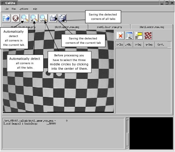
a) Run the automatic corner point detection for the first image/tab.
b) If the circles of the calibration pattern have not been recognized then either enter an appropriate binarization threshold in "Options->Settings" and return to step 2.a) or run semi-automatic detection and do click in the circles of the calibration pattern.
c) If no or too few corners of the calibration pattern have been detected in spite of correctly detected central points then lower the confidence threshold in "Options->Settings" and return to 2.a). The images probably present low contrast.
d) Run the corner point detection for all images/tabs with the above configuration.
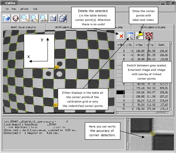
e) Check the result by for example using the "repaint grid"-icon at the top of the table. The detected corners are then linked by a line to their horizontal and vertical neighbors. Wrongly identified points can easily be detected. Either
i) select these points in the table on the right hand-side and click on the "delete-point"-icon to remove these points or
ii) adjust the parameters as in 2.b) or 2.c) in order to repeat full-automatic detection.
The last resource for really bad images is manual corner point localization. For this purpose, select a corner point in the table on the right hand-side and then click on the corresponding point in the image. However, this kind of adjustments are only very rarely needed. - Save data.
Save the detected corner points for all the images/tabs by clicking on the "save-points-of-all-tabs"-icon.

CalDe GUI 1

CalDe GUI 2
DLR CalLab
- Preparation.
Run DLR CalDe or any other similar program to detect and identify features of a particular calibration object. - Load data.
Load the PNG image files as in DLR CalDe. The application is flexible to the names and numbers used. At least three images (or stereo image pairs) are required. You may select more than one file at the same time by pressing the SHIFT key and selecting the first and the last file, or by pressing the CTRL key and selecting each file. Load the corresponding points files for the images as from DLR CalDe. - 1st Calibration Stage.
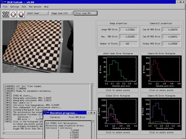
The general settings should not be actually modified in a standard calibration case. Documentation in this concern is pending. If you are ready for the parameters estimation (look at the text output) do proceed with the 1st calibration stage. Intrinsic camera parameters (including the camera-#1 to camera-#n transformation(s) in the case of a stereo camera rig) are going to be estimated. At the beginning a first estimation is done based on homographies (refer to the work of Zhang or Sturm and Maybank). Then, this estimation is numerically optimized. After that the points projection errors are overlaid on the images. You may browse through the images in order to look for mistakenly detected points. For this, it is useful to hide the actual image (click on 'switch monochrome image') and to augment the error arrows (click on 'error zoom'). In addition, you may use the histograms for rapidly finding mistakenly detected points. Repeat this 1st calibration stage if you did remove any point. - 2nd Calibration Stage.
The 2nd calibration stage supplies the TCP-to-camera transformation, in other words the hand-to-eye transformation. This transformation is not always required by the user and can only be estimated in relation to the TCP-to-robot-base transformations for every calibration image. These transformations were already read in DLR CalDe and also embedded into the points file. DLR CalLab offers different algorithms for estimating this transformation ("Settings->General settings"):
a) On the one hand you may use the method of Strobl and Hirzinger [Strobl06] minimizing errors in the erroneous world-to-TCP transformation. Here we use a particular implementation where the residual errors in distance are supposed to be mainly at the top of the manipulator - refer to the paperwork. The algorithm uses a linear least squares solution for the first estimation.
b) On the other hand you may minimize the features projection errors. This is a sound solution only in the case of highly noisy cameras with very low image resolution. - 3rd Calibration Stage.
The 3rd calibration stage only verifies the correct estimation in the last steps and furthermore produces accuracy estimations for the positioning device (e.g. robotic manipulator, infrared tracking system, etc.) responsible for the world-to-TCP estimations. - Save data.
"File->Save" saves the calibration results in the desired output format. For information on these formats refer to the text in "Help->Documentation" in DLR CalLab.

CalLab
Calibration hints:
Credit:

Credit:
- Make sure that the camera(s) are rigidly fixed to each other (in the case of a stereo camera rig)
or with respect to (w.r.t.) the pose tracking device (e.g. a robotic manipulator or an infrared tracking system).
- Focus the cameras to their eventual operational range. Choose a bigger aperture size if you need much light (or shorter shutter times) and you can afford a reduced sharpness region. Choose a smaller aperture size if you want do see sharp for a longer range. Fix these settings e.g. using screws. Handheld camera calibration asks for bigger aperture sizes for shorter shutter times. Static camera calibration rather has smaller aperture sizes for extended sharpness regions. Generally speaking, the camera parameters should be set to meet the eventual operational needs and not to optimize calibration performance.

Credit:
- Choose shutter times that do not overexpose the white regions of the pattern -- aim at gray rather than white. Otherwise sensor elements (sels) saturate and, what is worse, affect their neighbor sels, which lead to biased detection results using DLR CalDe. It usually comes in useful to choose automatic shutter times for the camera to dynamically maximize them without suffering from pixel saturation.

Credit:
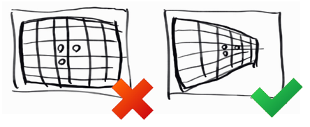
- Try to fill the images with corners. It doesn't matter if part of the calibration pattern cannot be seen. A complete coverage of the image area is paramount at as many images as possible. If the pattern is too small (e.g. if the camera is focused to longer distances and your pattern is projected in smaller areas -- even if it is size A2 or A1) you should opt for central projections.
- Note that at extremely short ranges the pinhole camera model doesn't hold anymore and the actual light path through the lens unit has to be considered instead. It is conventionally accepted that the pinhole camera model is only valid beyond close distances of approximately 30 times the focal length (Luhmann et al., 2006; Magill, 1955; Brown, 1966; Fryer; Duane C. Brown, 1986) -- I personally find this value too conservative. Bigger aperture sizes may aggravate the problem, calling for more complex camera models like the thin lens or even the thick lens camera models.
Credit:
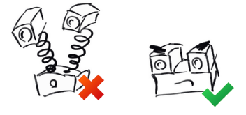
- Take oblique images w.r.t. the calibration pattern. Using orthogonal images it is impossible for the calibration algorithm to tell pattern range from the camera's focal length (i.e. magnification) or the pattern's absolute scale (if released). You may expect that orthonormal images are neither detrimental nor beneficial to calibration (of course, they are beneficial to the estimation of the distortion parameters), but simulations show that they really are detrimental to calibration accuracy in the presence of noise.
- You can start DLR CalDe multiple times and process different sets of images in parallel (the optimal number of DLR CalDes may be 3-4). This may be helpful as DLR CalDe (unlike DLR CalDe++) isn't really programed to use parallel threads. Bear in mind that simultaneous images using different cameras of the stereo rig have to be processed within the same DLR CalDe instance. After successful recognition, save all points files in the same folder. Or use the C++ version of CalDe.
- In the case that DLR CalDe performs badly because of the low contrast of the images, you can use Florian Steidle's GIMP script for stretching the brightness levels of calibration images here: gimp_stretchlevels.sh.zip (PNG files are expected).
- Do not bother to delete erroneously detected corners in DLR CalDe. DLR CalLab is best suited for that by using the residuals histogram plots on the right-hand side after a standard calibration attempt including erroneous data.
Credit:
- Use an accurate calibration pattern, e.g. of solid, metal finishing.
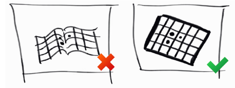
If you don't use a precision calibration plate, you may want to use the structure estimation options of DLR CalLab (Settings -> General settings -> Refine object structure). If you choose not to use the structure estimation options, then make sure that you accurately measure the calibration plate and fill in the data in DLR CalDe, or create a.cfgfile. In order to measure the calibration plate, do not measure just one square but as many as you can, and then divide the result by the number of squares -- in both main directions. If your calibration plate is not rigid, you should move the camera around the (static) plate. If your stereo camera is not synchronized, you should move the plate (and keep it in place) around the camera's FOV. (If both happens, then you're screwed my friend.)
- If you are not totally free to take the optimal intrinsic camera calibration pictures during extrinsic camera calibration, we suggest to detach intrinsic from extrinsic camera calibration. First, take the optimal intrinsic calibration images and perform intrinsic calibration. Save the results in the RMC file format. Then, take the optimal extrinsic calibration pictures, load them in CalLab, and load the former intrinsic camera calibration file as well. Go to Settings->Intrinsic camera parameters and fix all intrinsic parameters (perhaps from both cameras). Then proceed both, with a (restricted) intrinsic camera calibraton and with an extrinsic calibration. The final result will feature the optimal intrinsic camera parameters estimated before.
- During extrinsic calibration, the user can select the transfomation where errors are expected -- the errors will be minimized according to Ref. strobl:2006iros. In the case of eye-in-hand robotic systems it is customary to expect the errors on the robotic manipulator, hence base->tcp should be considered as erroneous. There are occasions, however, where the errors are expected in the camera pose estimation algorithm (e.g. intrinsic camera calibration), e.g. in the case of cameras with narrow angular field of view (refer to strobl@2009iros_) and precision pose tracking systems (e.g. laser trackers). On this occasion, errors are expected in the camera->object transformation, and more specifically the translational errors are in the position of the object frame.
- You can readily use DLR CalLab to estimate the pose of the calibration pattern with highest accuracy: By fixing the intrinsic parameters to previously optimized ones (by loading a previous calibration file) DLR CalLab will only optimize the extrinsic pose of the calibration plate w.r.t. the camera(s). This estimation is even more accurate than during camera calibration, as the intrinsic parameters are already both fixed and optimal. It is worth noting that DLR CalLab still uses the same methods as in the case of regular camera calibration for the initialization of the parameters, thus at least three different images are needed. You can simply use two images of the latest camera calibration together with the current image from which you want to estimate the pose. After that, the optimal extrinsic poses are produced either in the console or by saving calibration results in the Matlab format.
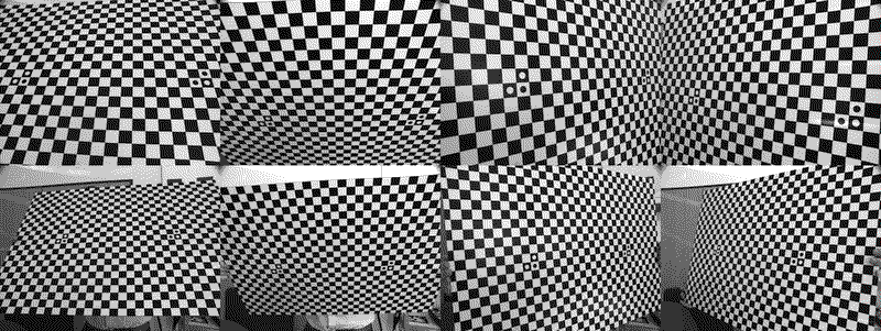
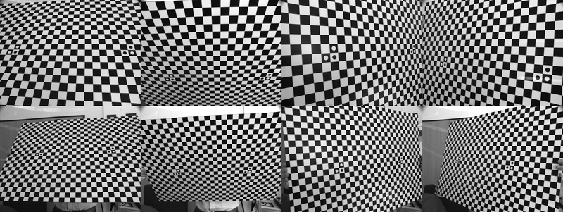
CalLab sample calibration images
Calibration image set example composed of a eight images. Note that all images are tilted w.r.t. the calibration plate; note that at least the closest images (upper row) are filled with features; and note that the tilting angles are symmetrically distributed (up, down, right, left -- from left to right in the image). We usually take a second set of four images further away (bottom row) in order to further constraint the estimation of the relative position of cameras within a stereo camera rig (viz. the squint angle). In the case of monocular cameras, however, the upper four images suffice.
Warnings:
- Beware of possible malfunction of the image reading function within DLR CalDe when using TIFF, PGM, or PPM files. Depending on the version of the IDL Developer software where the code has been compiled, the IDL image reading function may mirror these images w.r.t. the horizontal axis! We therefore recommend to always convert your images to PNG format prior to calibration (e.g. using the convert tool in Linux).
- Note that when using stereo cameras, the rotation matrix R between cameras is similar to inv(R) so that your code could still work, even if the inverted rotation is used by mistake. E.g. OpenCV's rectification functions require inv(R) and T.
- There is an unexplored issue when extrinsically calibrating (i.e. hand-eye calibration) cameras mounted on a pan-tilt unit. The requirement for two rotations with orthogonal axes of rotation still holds. The absence of any translation, however, allows for a virtual, valid solution when world_T_tcp is erroneously considered its inverse. Since DLR CalLab summarily tries both directions world_T_tcp and tcp_T_world in case the user provides wrond data, keeping the result with the lowest RMS, it is fairly probable that you will end up in the symmetric, virtual solution that delivers a lower RMS error but does not correspond with reality. To avoid this, make sure that you provide the transformation in the correct direction (world->TCP) and that you disable the option to try world_T_tcp in both directions in Settings->General settings, and also take a sufficient number of (asymmetric?) images.