
DLR Laserscanner (2000)
Principle
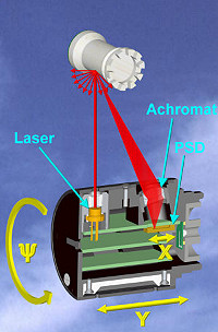
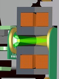
The DLR Laser Range Scanner is a device for the exploration of three-dimensional environments. It uses the principle of laser triangulation, as shown in Figure 1. A laser beam is send from a source and will be dispersed diffusely on the scanned object's surface. Some of the reflected rays strike a lens which focuses the light onto a sensitive area of a position sensitive detector (PSD). Thereby the position of the focal point on the PSD in X-dimension changes with the angle of incidence on the lens which on the other hand depends on the distance between sensor and the scanned objects surface.

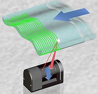
This method measures only one range value at once. The system has been improved by embedding the triangulation modul in a rotating device. Thus a 2D-slice of the environment can be measured at once.

Design
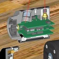
The triangulation principle has been realized in a miniaturised range-scanner device. It consists of a rotating scanhead, a motor, an indexing system and a controller box. The figure shows the device, for the weight and the metrics see the Data Sheet.
Scanhead
The scanhead contains all parts that are necessary for triangulating and computing the range values. These are the laser diode module, the receiveroptics with an achromat and the position sensitive device (PSD), and the complete elcetronics for computing and transmitting the sensor data.
The DLR laser diode module used in the scanhead emits a laser beam of 670 nm wavelength. While commercial modules show deviations of up to 7° between the laser beam and the axis of the housing, the DLR module can be adjusted precisely. With its dimensions of Ø9 x 11.5 mm it generates a laser beam of Ø1.2 mm and 2 mrad divergence. The deviation of the laser beam and the module's housing is reduced to a value well under 0.1°. The laser diode being electricaly isolated, is thermicaly well coupled to the module's housing. The scanhead serves as a heatsink in order to increase the on-time of the laser. The PSD-signal is processed by the electronics of the scanhead. For the distance measurements 12 Bit resolution are achieved, whereas the intensity of the sensed light spot is transmitted by a 4 Bit signal (logarithmically).
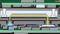
Splitted into three boards, the scanhead's electronics also controls the laser diode, the data transmission and the contact-free, inductive power supply. The bi-directional data transmission connecting the rotating scanhead and the chassis is realized by optical communication components of ELCOS. With these IR emitting/receiving SMDs a data transfer rate of 1 MBit/s can be achieved. The contact-free data transmission guarantees wear-free and robust operation of the system. The power supply of the scanhead is also realized contact-free. Two transformer coils embedded in ferrite cores are integrated vis-a-vis in the scanhead and the scanner's chassis respectively. The air gap between the two cores can be adjusted to a value well below 0.1 mm. The assembled power and data transmission unit is shown.
Motor
The Scanhead is driven by a modified stepper motor of PORTESCAP. By using a stepper motor, the speed can be regulated very fast by referencing a optical index with the incremental rotation angle of the motor control. At the startup the motor speed is increased along a ramp function to 1500 rpm (25Hz), a speed where the measurement can be synchronized with external video clock. The motor is supplied with 24 Volt, whereas the electronics run at 5 Volt(DC).
Indexing
After motor startup, the scanhead rotates with a constant speed. An optical double-mirror which is integrated into the scanhead serves as a reference and reflects the light of a IR-LED onto a differential photo diode (both chassis-mounted). The actual rotation angle is calculated from the durations of the last and actual rotation.
Controller Box
The controller box contains the motor driver ,the CAN-interface and a micro controller which provides basic controls (e.g. on/off). The range data and the rotation angle are correlated by the controller and transmitted via CAN. In addition the active scan angle is adjusted. In the range of the maximum scan angle of 135°, an arbitrary segment can be defined where the scanner performs measurements. Measurements and laser diode are switched off in the other segements. This feature is important for safety reasons and for the reliability of measurements in multi-sensor systems (e.g. additional video cameras). The field of view (FoV) can be focussed on interesting areas. Furthermore the controller has an BNC-port to synchronize the scan cycles with an external video source.
Datasheet

Height | H =42.0 mm |
Width | B =32.0 mm |
Length | L =75.0 mm |
Weight | G=180g |
Min. Scan Distance | DMIN=53 mm |
Max. Scan Distance | DMAX=300 mm |
Max. Scan Angle | ßMAX=270° |
Scan Angle Resolution | ? ß=0.9° |
Sampling Rate | f=10kHz |
Interface | CAN Bus |