
Laser-stripe Profiler (2003‒2007)


Design
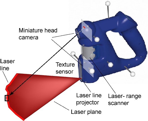
The fundamental principle of range sensing by optical triangulation is illustrated in this figure. A focused plane of laser light illuminates a stripe on the surface of an object. A video camera (in our case without optical filtering) records its reflection. 3-D reconstruction is performed by triangulation, intersecting the laser plane with the rays of sight corresponding to the laser stripe projection in the image frame.
Note that this principle of operation is very much alike the one of stereo-vision systems. A laser plane is used instead of a second camera in order to simplify the correspondence problem. In this way, the major obstacle for using stereo vision in 3-D modeling at high-rate -- the computational requirements -- can be overcome.
System Calibration
The accuracy of the laser stripe profiler heavily depends on the calibration process. The sensor must be calibrated with very high precision regarding both, its geometric and its optic characteristics.
The calibration of the video camera calibration has been performed using the DLR CalDe and DLR CalLab camera calibration toolbox.
The laser plane calibration is the process of determining the relative pose (position and orientation) of the laser plane with respect to the sensor reference frame. This is a particularly critical point since its miscalibration leads to misalignments and warpage effects in the resulting surfaces during scanning. We implemented a novel self-calibration method that is based on the assessment of the deformations this miscalibration leads to.
When estimating the pose of the laser plane there exist three independent Degrees of Freedom (DoF) to be identified. Different solid-geometry reconstruction errors follow from imprecision in the estimation of each of these DoF, for every scanning motion of the hand-guided device. These include from simple scaling errors up to convex/concave warped deformations, or even irregularly warped results.
Our self-calibration method works as follows: First, the reconstruction process runs with some initial laser plane calibration parameters that have been roughly estimated a priori. The proposed method exploits the distortions that appear during this initial reconstruction process. As a calibration surface we use a plane of unknown pose, both in order to avoid the construction of a complex calibration target and due to the fact that a plane has the geometrical shape that can be validated in the easiest way. After scanning the calibration plane, the reconstructed pointcloud features unevenness if scanned from very different points of view -– theoretical studies determine the ideal procedure. Subsequently, the best fitting calibration target plane for these points is estimated –- this overdetermined problem is solved using a closed-form solution in the form of a Singular Value Decomposition. Finally, the optimized laser plane parameters are estimated off-line -- the goal is to minimize the mean-squared distance of every reconstructed point to the best fitting plane. The Nelder-Mead Simplex method has been implemented for numerical optimization. Furthermore, an Extended Kalman Filter is used to estimate the precision of the obtained results.
To recapitulate, the laser plane parameters are adapted in such a way that, in the end, the scanned surface becomes as flat as possible.
Laser Stripe Segmentation
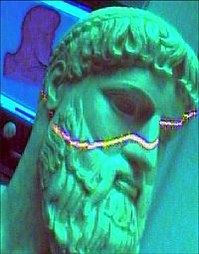
In order to extend the range of objects that can be scanned, the image processing algorithm does not have any precise a priori knowledge about the shape of the laser projections. This fact may yield erroneous results in the case of specular reflections or red light sources –- a standard segmentation algorithm would easily detect them erroneously as laser projections. Furthermore, the absence of optical filtering when gathering laser stripe images aggravates the susceptibility to errors. Hence both reasons ask for the implementation of a robust stripe segmentation method. Novel measures must be taken in order to reduce the number these types of failures.
Our approach is based on a stripe edges detection software algorithm. The algorithm for detecting both upper and lower stripe edges is based on the Sobel Filter. In addition, two validation stages have been implemented: color and line width validation (in the form of online look-up tables). Color validation copes very well with the problem of specular reflections and, in addition, it provides robustness and flexibility against changing lighting conditions. Width validation aims at blocking specular reflections of laser. It also corrects erroneous measurements when coping with object corners.
The central point of the stripe is eventually estimated to sub-pixel precision (to within a fraction of a pixel) by means of the center of mass method over the red image channel. Brightness saturation -- which is very likely in the case of non-filtered cameras capturing laser light reflections -- rules out methods like Gaussian approximation.
Single and Dual Crosshair Laser Stripe Profiler
It is usually said that scanning with this type of sensor is virtually like spray can painting -- particularly if the sensor is mounted on a hand-held device. This is not completely true, however, since you do not have the freedom to horizontally move in the direction of the stripe during gathering data, but only to sweep up and down the sensor. During automatic 3-D scanning by a robotic manipulator this fact constraints the motion of the robot and entails the waste of one DoF.
In order to avoid this constraint we use an additional laser beam that illuminates perpendicularly to the first stripe (from here crosshair). Due to construction-related constraints, both laser beams have to be placed close together. Since this arrangement implies an undesired reduction of the basis distances between each laser beam and the camera, we opt for using the second camera of the DLR 3-D Modeler in order for each of the cameras to perform single laser stripe profiler scanning with their farthest laser plane. We call this configuration dual crosshair laser stripe profiler. To recapitulate, the addition of a second miniaturized laser beam implies: 1) the release of one scanning motion constraint, 2) the increment of surface-related information gained in every direction, and 3) the possibility to duplicate the sensing data rate since both cameras and laser beams may be triggered in a complementary way, at higher speed and limited shutter time.
Error Modelling
In order to improve reconstruction accuracy and aiming to complement higher-level tasks like data fusion, exploration, and meshing, a stochastic model of the solid-geometry reconstruction process has been developed. This stochastic model joins together both, systematic and random errors, and it is parameterized in relation to the empirical calibration results.
References
K. H. Strobl, W. Sepp, E. Wahl, T. Bodenmueller, M. Suppa, J. F. Seara, and G. Hirzinger. “The DLR Multisensory Hand-Guided Device: The Laser Stripe Profiler.” Proceedings of the IEEE International Conference on Robotics and Automation (ICRA 2004), New Orleans, LA, USA, pp. 1927-1932, April 2004.