
ROKVISS - Robotics Component Verification on ISS
2010-11-15 ROKVISS completes its very successful mission (see ROKVISS Results)
For publications and videos see ROKVISS Results.
System and experiment description
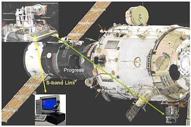
Germany’s recent space robot project ROKVISS was successfully launched on December 24th 2004 form Baikonur Cosmodrome. During a spacewalk on January 26th 2005, the ROKVISS experiment hardware was mounted to the outer wall of the Russian Svesda module.

ROKVISS aims at the qualification of the newest light weight robot joint technologies as developed in DLR’s lab. They are the basis for a new generation of ultra-light, impedance controllable and soft arms, which, combined with DLR’s newest articulated 4-fingered hands, are the essential components for future robonaut systems.
DLR’s focus on space robotics was driven by strong considerations, how to push robotic technologies for space applications. A new generation of light weight robots with an unbeatable weight to load ratio as well as impressive control features, which makes the system easy-to-use and safe for terrestrial servicing applications was developed. To test and verify all these new technologies in space, recently the ROKVISS (RObot Komponent Verification on ISS) Experiment was born. The main goals of the ROKVISS experiment are the demonstration and verification of light-weight robotics components, under realistic mission conditions in free space, as well as the verification of direct tele-manipulation to show the feasibility of applying tele-presence methods for further satellite servicing tasks.
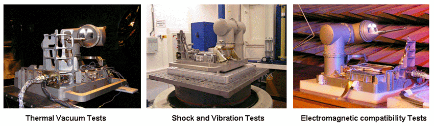
One basic idea for the ROKVISS project was to get rid of bulky and expensive radhard components for a space born application in favor of highly integrated circuits used with terrestrial devices. To come to a first assessment of the applicability of the joint mechatronics for free space, we performed a radiation, an EMC and a thermal test with one of the existing joints. The results of all these tests were very convincingly, no problem in principle could be identified.
Despite these encouraging test results, it was clear that some kind of redesign had to be done:
- Exchange cross roller bearing against two angular roller bearings
- Exchange all electrolytic capacitors against tantalum types
- The gear output position sensor from the Netzer company was not available, therefore a potentiometer based position measurement system was developed
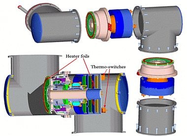
- All heat producing electronic parts need to be thermally coupled to the robot’s structure to allow for heat dissipation
- The optical SERCOS bus ring topology was modified into a point to point connection via copper wires. Each joint is coupled via SERCOS with the main computer (OBC). The advantage of the point to point structure is that even if one joint electronic fails the remaining joint is still operable.
- A latch-up protected power supply circuit had to be implemented
- Electronic parts with extended temperature range (-45 C to +85 C) are used.

|
In addition to the tests mentioned above, we verified the performance of our recently developed latch-up protection system at the ISL (ion beam laboratory), Berlin.
|
General Experiment Descriptions
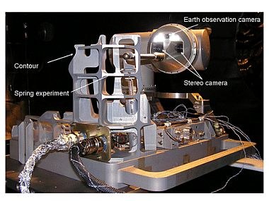
The ROKVISS experiment consists of a small two-joints robot, mounted on a Universal Workplate (UWP), a controller, an illumination system, a power supply, and a mechanical contour device for verifying the robot's functions and performance. These two robot joints will be tested for further use in free-space by repetitively performing predefined robot tasks in an automatic mode, i.e. without direct operator interaction. A priori defined joint trajectories will be sent to the on-board system then and performed autonomously.
For the tele-presence demonstration a stereo camera is mounted on the 2nd joint: The video images together with the current robot joint and torque values will be fed back as the current situation to an operator, located at DLR’s ground station. The operator controls ROKVISS robot via a force-feedback-control device. Force and position commands are generated, to drive the robot joints into the desired state. Using high-rate up- und downlink channels, the operator will be directly involved into the control loop. Crucial factors in gaining a high quality immersion of the operator into the remote scenery are high data rate, low latency and jitter-free force/position data as well as a reasonable good and up-to-date stereoscopic video transmission.
The stereo images from a stereo video camera, mounted to the last joint of the robot, are transmitted to the ground station together with the measured joint positions and current joint moments. The robot receives its motion commands from the ground station in real-time via an S-band communications link. The robot will be operated in automatic and tele-presence mode. The tele-presence mode can be used for up to seven minutes during the phase of direct radio contact, when the system passes over the tracking station in Germany (German Space Operation Center, GSOC). A major requirement for this mode is to keep the total data round-trip-time significantly below 500 milliseconds (the real round trip time for ROKVISS is below 20 ms). In automatic mode, the system goes through selected, predefined motion sequences. The measured joint data will be stored on-board and transmitted to ground during the next radio contact phase.
Scientific Goals
The main elements of the ROKVISS experiment are the two light-weight robot joints, which should be tested and verified under free space conditions for further missions. Most of the ROKVISS experiment time will be used to set the robot joints into continuous operation to record all the interesting data for further analysis on-ground.
For satellite repair and servicing tasks, the direct inclusion of a human operator into the control loop is inevitable, due to the fact, that such missions couldn’t be prepared in detail off-line on-ground. Therefore a tele-operation mode must be provided, which gives the operator the feeling to do the job directly at the remote site. Especially for operation in geosynchronous orbits, this tele-presence mode could be applied around the clock because of unlimited radio contact. Such a classical master-slave tele-operation mode has the advantage to minimize the efforts on H/W and S/W on-board. On the other hand, very high demands are given onto the data communication w.r.t. to the jitter of the data transmission as well as the entire round-trip time.
Tele-Presence Mode Experiments
As mentioned above, for all the space robotics applications, which can be imagined in the field of servicing, the direct inclusion of a human operator into the control loop is inevitable, because such missions couldn’t be prepared in depth off-line on-ground. Therefore a tele-presence mode must be provided, giving the operator an immersive feeling to do the job immediately at the remote site. The most significant problem is the time delay between the command generation on-ground and the arrival of the feedback data from the remote robot system. Many attempts have been made to compensate or overcome these problems. Model-based approaches, e.g. using predictive graphics, are very helpful, if an accurate geometric and dynamic model of the remote environment exists. Signal based methods can handle varying time delays. But, to achieve a good immersion, the best way to do this, is reducing the time delay and eliminate possible jitter in data transmission.
For the tele-presence demonstration the operator controls the slave robot at the remote site via a force-feedback-control device. Force and position commands are generated to drive the robot joints into the desired state. Using high-rate, low latency and jitter up- und downlink channels, the operator will be “immersively” included in the control loop. A major requirement for this mode is to keep the total data round-trip-delay significantly below 500 milliseconds. Indeed for the ROKVISS direct over flight situation we maesured only 15-20ms roundtrip delay, but we will also introduce additional time-delays to simulate tele-presence operation via a geostationary communication satellite.
While large and varying time delays can be compensated by model based approaches, e.g. using predictive simulation (as demonstrated in ROTEX), we will have a strong signal based coupling between the ground operator and the space robot. First the force feedback loop is realized with a common position / force control structure. To cope with longer and varying time delays, sophisticated bilateral control structures are used.
The evaluation contour, mounted to the ROKVISS base plate, is used to verify the tele-presence control schemes under realistic mission conditions.
- The contour represents a hard surface, which may be contacted with the stylus.
- Different geometrical forms are included for contour following tasks.
- A 2 DoF “Peg in Hole” part realizes a 3 direction mechanical captivation of the stylus.
- Mechanical springs simulate an external energy storage, which can add energy to the Master-Slave system.
- A virtual spring is programmed into the robot joints to emulate different surface stiffness. The operator has to follow a well defined virtual path which fades in into the video display . While performing this task the robot is fixed at its position by means of the “Peg in Hole” part. The difference between the measured and commanded robot position represents the feedback force.
Tele-Robotic Mode Experiments
During direct radio contact the remote robotic system can be commanded by an operator via the supervisory control techniques as realized in the man-machine-interface (MMI) of the MARCO tele-robotic ground station. Feedback will be provided via the on-board camera system and the telemetry data. All the force-controlled tasks can be executed by sending a predefined path to the on-board system. In contrast to the automatic mode experiments (below), these experiments are conducted via direct operator interaction. This means, that all experiments as described in the following section, which do not exceed the link coverage time, may be performed in tele-robotic mode, too.
Automatic Mode Experiments
The main purposes of the automatic mode experiments, automatically activated several times via the mission timeline, are:
- the long-term verification of the joint’s behavior during free space operation as well as
- the dynamic parameter identification under free space conditions.
These experiments are a very good means to obtain comparable data sets of joint parameter. The experiment data (robot paths and control modes) are up-linked prior to their execution. The automatic mode experiments will be automatically activated via the mission timeline, independently of direct RF contact. All measured joint parameters are stored on the on-board storage device and down-linked on demand during the next radio contact phase.
The following experiments will be conducted:
- Predefined trajectories without force contact, to test the joint’s behavior during non contact operation.
- Predefined trajectories with force contact, i.e. contour tracking or movement against a spring load (force control, Cartesian impedance control).
- Predefined trajectories with a change from non-contact to contact condition (contact dynamics experiment).
Dynamic Parameter Identification
The dynamic behavior of robotic motion simulation and hence the operational overall performance depends on a large extent on the validity and reliability of the underlying dynamic models. In the micro-gravity and hostile space environment the dynamic behavior of robotic manipulators is quite different from their on-ground behavior. In-flight dynamic data therefore are required, with the primary goals to update and validate mathematical models and to gain increased confidence in the modeling process, especially w.r.t. more advanced servicing missions.
To increase confidence in the dynamic modeling process and in ground-based simulations, the proper knowledge of system parameters, especially in the non-linear joint dynamics, is very important. Therefore, we use ROKVISS also as an in-orbit testbed for verifying methods for dynamic parameter identification and for identifying the unknown parameters in situ. ROKVISS provides an outstanding opportunity to close that gap.
Accurate dynamic models for guaranteeing expected manipulator performance in micro-gravity environment are required for both the pre-mission development and testing phase and for the final in-flight operations phase. The effects of strongly reduced gravity and temperature changes as well as the expected physical parameter changes due to material degradation, act severely on the proper modeling of joint non-linear dynamic behavior (Harmonic Drive gear type). This influences especially effects such as friction, stiffness, and control. In-flight identification of system parameters and dynamic model validation is therefore a prerequisite to gain increased confidence in the modeling process.
The objectives of the technological experiments are:
- to identify important dynamic non-linear system parameters in micro-gravity environment and to validate the underlying multi-body system models,
- to increase modeling fidelity and hence performance quality for future robotic missions in low earth and geo-stationary orbits or any other space-based robotized platform.
Joint Parameter Identification
For the design of the joint level controller for the DLR light-weight joints (position, torque, and impedance control), efficient and reliable autonomous off-line identification methods have been developed, which provide the stiffness and damping, as well as the friction parameters. These identification methods will be used for the estimation of parameters for controller design during the mission. Starting from the model and the corresponding identification measurements, a modified time-efficient, on-line identification procedure based upon Recursive Least Squares algorithms has been successfully tested on ground and will be used for the identification.
Contact Dynamics Experiment
The Canadian Space Agency (CSA) uses the ROKVISS facility onboard the ISS to study how the space environment affects the behavior of bodies interacting together in a contact situation. Specifically, the project proposes to measure
- the energy dissipation occurring during intermittent impact events, as well as
- the frictional forces acting between two bodies while they are moving w.r.t. each other in a lasting contact situation.
Three different environments will be used to study how the space environment affects the contact model parameters:
- On Earth under standard atmospheric conditions, using the ROKVISS backup or engineering system to perform a set of contact tasks.
- In a thermal vacuum chamber, by means of a special apparatus designed to measure very accurately the friction coefficients. The experiments are performed at various temperatures varying from standard atmospheric to space like conditions.
- On-board the ISS, perform the same experiment as on Earth.
For publications and videos see ROKVISS Results