
Electrodynamic Shaker

Your consent to the storage of data ('cookies') is required for the playback of this video on Youtube.com. You can view and change your current data storage settings at any time under privacy.


When developing components exposed to vibration, the investigation of fatigue strength of materials and entire components or even groups of components is a decisive safety factor in the FEA analysis and especially also to the constantly running component. These High-Cycle-Fatigue (HCF) tests are carried out at our institute using an electrodynamic shaker.
In the component design and manufacturing technologies department, for example, components are calculated analytically using FEA methods as part of engine component development and optimised together with aerodynamics and aeroelasticity. These structures are also built and tested.
In any case, the material samples and components must be tested for fatigue strength with high-cycle fatigue measurements and are subject to strict criteria as to the load range in which they may be present in order to withstand long-term loading. Likewise, the quality of the calculation can be verified by comparing the properties between the FEA and the real part.
Materials are significantly weakened by long-term and correspondingly high loads. This weakening is shown and evaluated for the material, for example, in a Wöhler diagram or Goodman diagram, and for a component, for example, in a Campbell diagram. All diagrams require the object to be loaded on an electrodynamic shaker as long as and as high as necessary until it fails.
Normally, the object is subjected to a sinusoidal load at room temperature and direct air cooling for 10 million load cycles for each load level and the load (amplitude) is increased by at least 15% after each cycle. The test is mainly carried out in resonance (1st mode) to be able to apply the necessary energy and have a reference point for proper control as the object becomes increasingly softer. The control parameters here are the max. amplitude and the phase angle between stimulation and response. Likewise, the information about the resonance frequency itself is important for comparing with the FEA calculation. This natural frequency can be stimulated and measured non-destructively with the shaker but also with a stimulation hammer. Acceleration sensors as well as distance measuring lasers are used for this purpose. The data is evaluated by a control computer, which simultaneously sends the control input to the shaker amplifier.
But the shaker system at the institute can do a lot more: For example, noise stimulation (random) or shock movement up to 2 inches is also possible. Both can be used, for example, to test some space parts for their suitability in everyday use during the launch process.
With the new sliding table, which can be flange-mounted to the tiltable shaker, it is now possible to test objects around all three axes. Until now it was only possible to test objects normally in the Z-axis on the shaker, they can now also be tested on the sliding table along their X- and Y-axis.
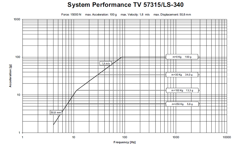
Key data Electrodynamic Shaker
Nominal force | 15 kN |
Frequency range | 20 - 3.000 Hz |
Max. vibration displacement | 2 inch |
Max. acceleration | 115 g |
Max. load capacity | 250 kg |
Types of use | Sine / Noise / Shock |