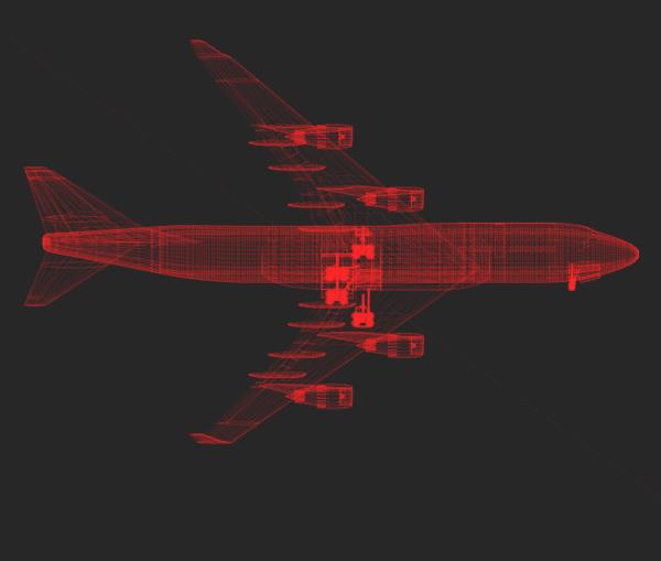
Every simulation starts with an as accurate representation of the reality as possible. This is achieved by detailed 3-D surface model data of the object of interest. In the case of Figure 1 the wireframe model data represents a Boeing 747.
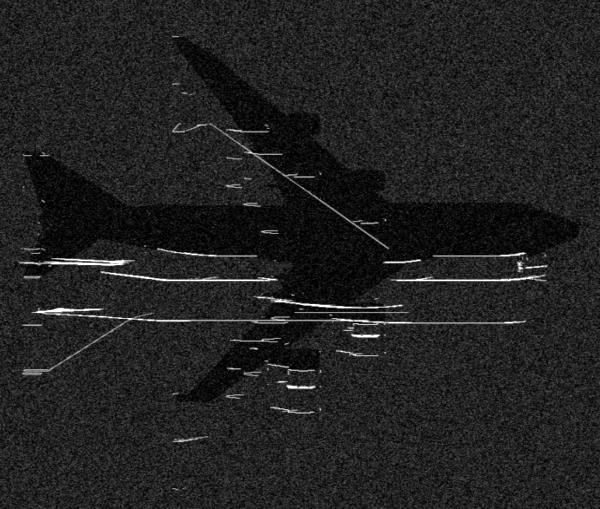
After setting SAR acquisition parameters like the attitude and the radar system configuration, a fast ray-tracing method finely samples the object of interest. Our approach not only finds the prominent scattering effects of the object, but also localizes them in the SAR image plane and calculates their reflectivity through sophisticated and highly runtime-efficient algorithms. The visual result of this step is called a reflectivity map and is illustrated in Figure 2 for the chosen Boeing 747 airplane.
Such a reflectivity map can be assumed to be an ideal SAR image, because it lacks effects like finite bandwidth or side lobe effects. Additional to the prominent scatterers, also the clutter return and the shadow of the airplane are included into this reflectivity map.
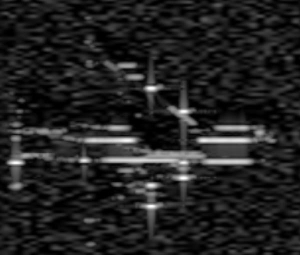
The final step in the simulation process has the task to take this ideal SAR signature and process it to a more realistic one. This is done by fast image reconstruction techniques that reduce the bandwidth of the reflectivity map by using the impulse response of the considered SAR system. The resulting simulated SAR signature as would be expected from a high resolution spotlight mode TerraSAR-X system configuration is illustrated in Figure 3.