Try to remember the last time you took an airplane. If you have to think about what elements of that flight played an important role in cabin comfort, chances are that within the top five of that list you included cabin noise.
Cabin noise is understood as a vibroacoustic problem, in other words, the noise is a direct result of the undesired vibrations of the aircraft fuselage. There are multiple sources that contribute to the fuselage vibration such as engine sound radiation, turbulent boundary layer, engine related vibrations, etc. Hence, understanding what drives the fuselage vibrations and how these contribute to cabin noise is a crucial element of research in vibroacoustics.
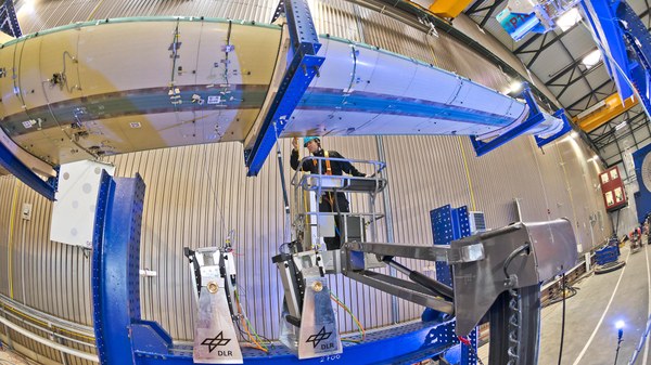
In order to correctly quantify the energy propagation and sound radiation of the fuselage, it is usually necessary to perform measurements with a spatial resolution smaller than the wavelength of interest. For a relevant structure, such as an aircraft fuselage, this means ending up measuring hundreds or even thousands of data points. Although technically still possible, these types of large-scale measurements are very challenging and time consuming. Specially the installation phase of the experiment where each precise location on the structure needs to be identified first and then a sensor must be precisely prepared and installed. A connecting cable between sensor and data acquisition system must be routed. One cable per sensor, in total hundreds of them.
Development of our own tools
The interest in this vibroacoustic field has gained so much momentum in the last decade that these types of large-scale measurements have become rather usual. As a result, the Vibroacoustics Group at the Institute of Aeroelasticity started years ago to develop test procedures in order to simplify and speed up these experiments.
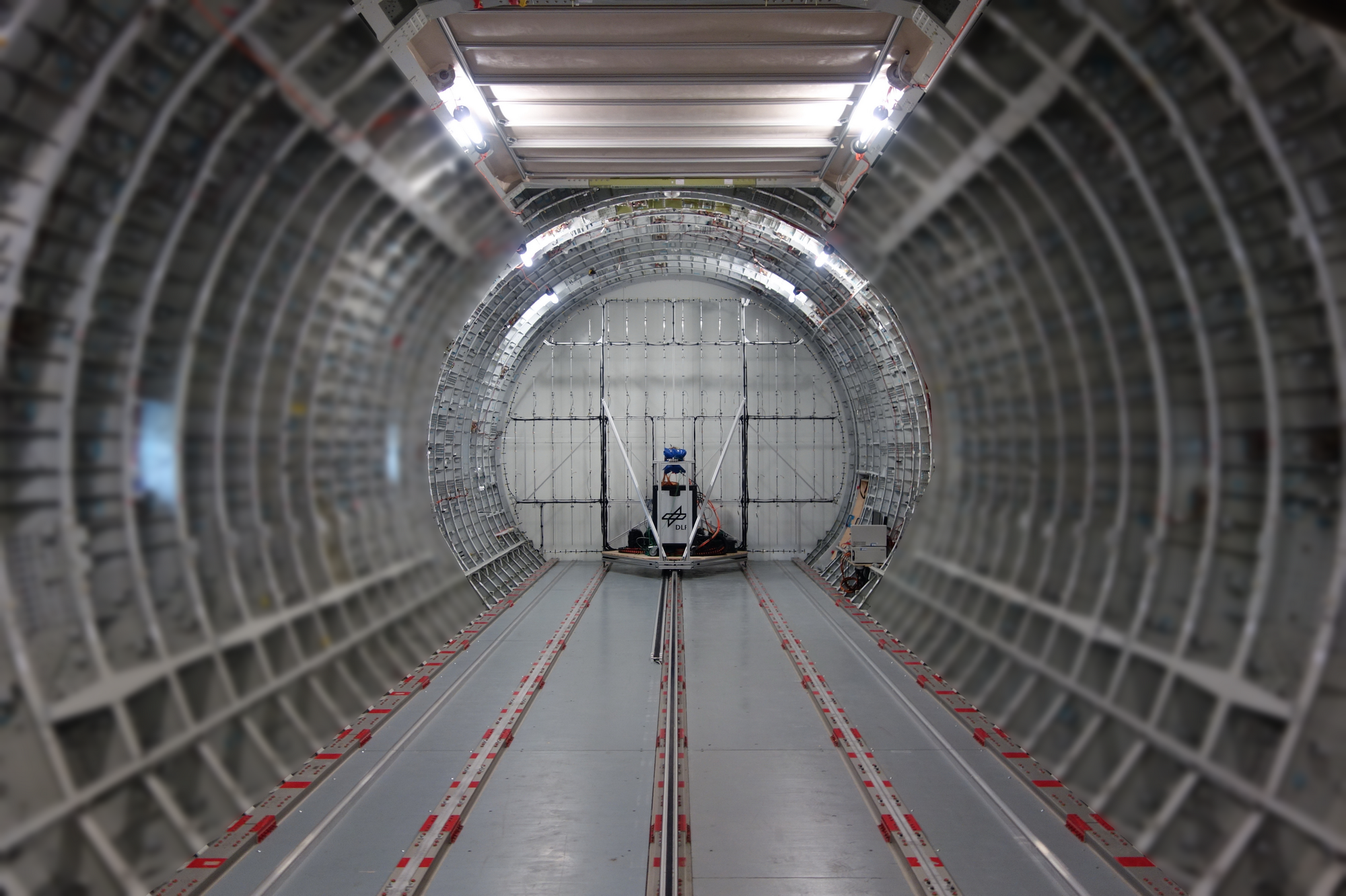
The goal was to develop an automated system able to measure fuselage vibrations in the simplest way possible. As it usually works in research, you have to go through a couple of iteration when you create something new, in order to improve and refine whatever you are developing. After a couple of years of development and testing, the Fuselage Laser Scanner (FLS) was borne. It is composed of a Laser-Doppler vibrometer, servo motors, mirrors to manipulate the optical path of the laser beam, a CCD camera to verify the laser point position and to identify QR markers, a data acquisition unit to measure the vibration response and to control the excitation, a vibration isolation system, and a control unit able to perform fully unsupervised measurements once that system is configured. All that combined with the autonomous ability to find and position itself within the measurement grid by using a set of reference QR markers placed on the structure.
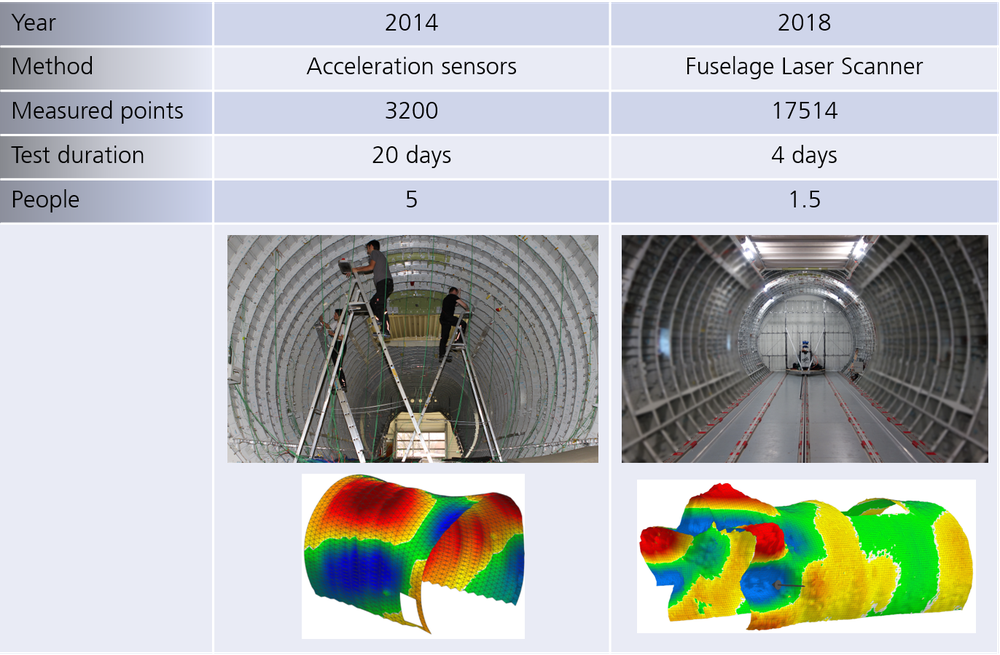
Since the start of the development, the FLS has been tested, validated and put into production multiple times. Providing a significant advantage over the “classical” sensor-based measurement procedure performed in the past. In order to put this into perspective, two measurement campaigns will be compared. Both performed on the same structure, a fuselage of an Airbus A400M where a section of 12.5 m was measured. As can be noticed, the improvement in all categories is quite significant.
Comparison of the measurement campaigns 2014 and 2018
The capability of the FLS to measure fuselage vibration is a remarkable advancement in state-of-the-art metrology for vibroacoustic tests on aircraft fuselage. The FLS covers just one part of the data acquisition that is relevant in vibroacoustic research. There are a number of other topics that usually require different types of data, for example, sound radiation, energy transmission and dissipation, etc. For such cases, sensors like intensity probes, automatic modal hammers, stereo camera systems, etc. are needed. And more importantly, you need to get closer to the structure to perform proper measurements. Although the FLS is a remarkable tool, it was not designed to carry out all these types of measurements.
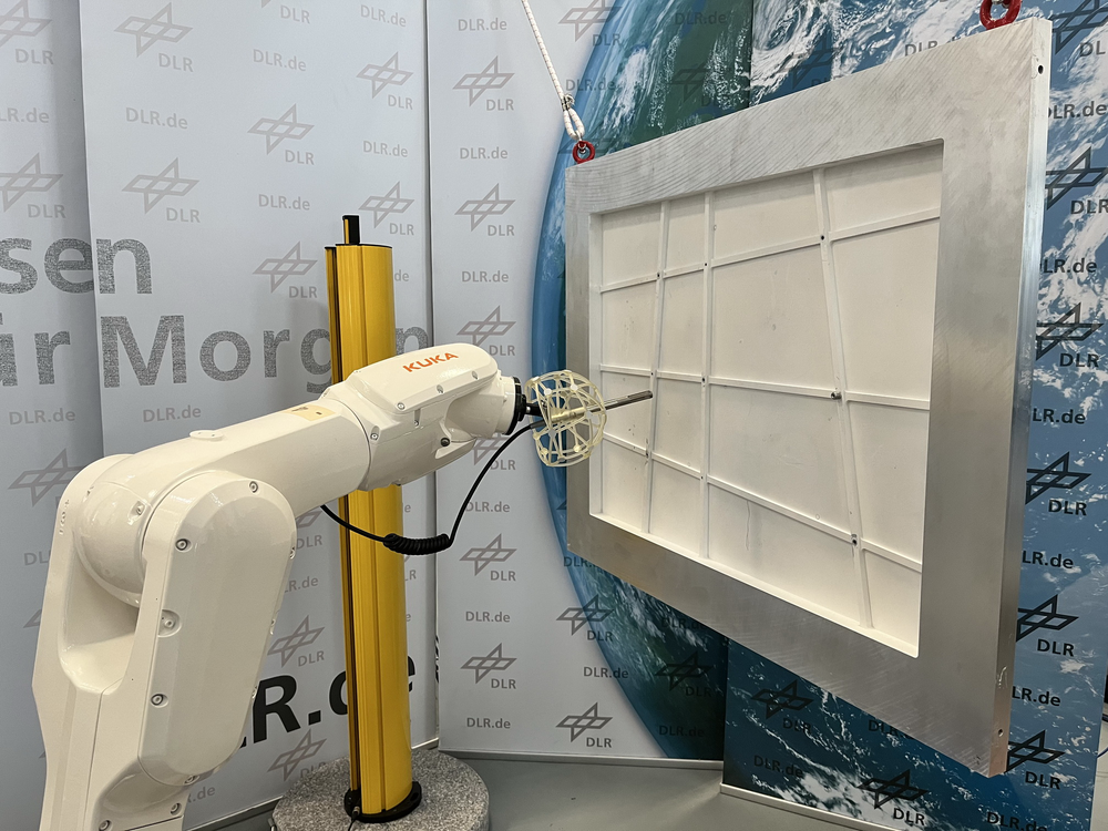
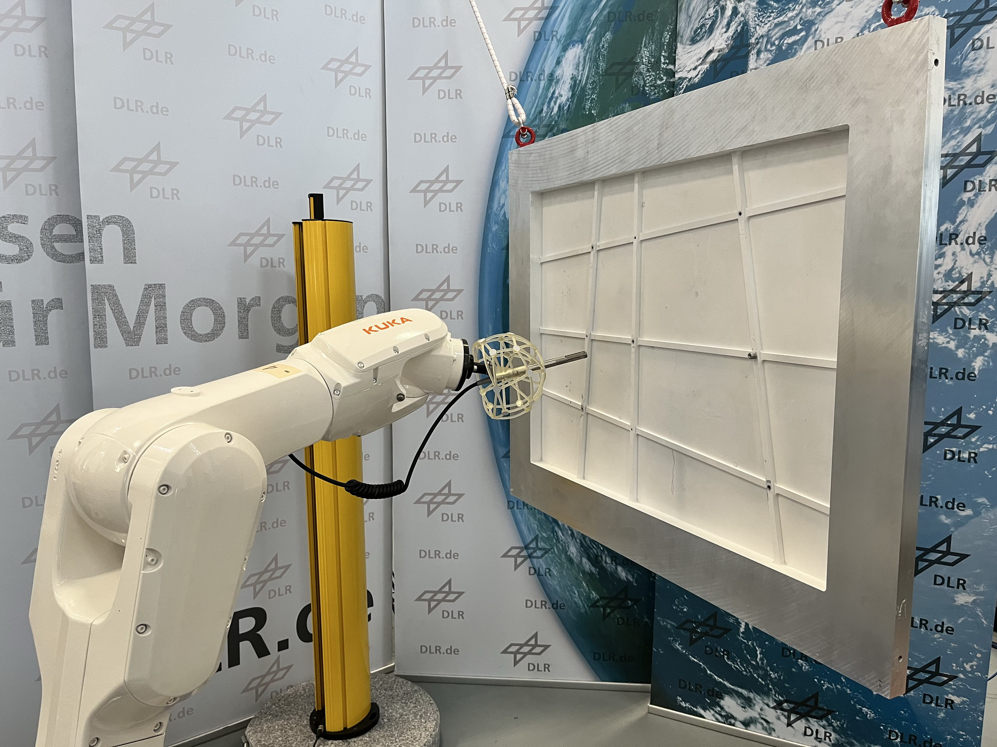
If we envision for the future a new tool that would help us with such challenges and at the same time provide enough flexibility, a robotic arm could fulfill all these requirements. With such platform, we could attach different sensors as needed, get closer to the structure, be able to scan almost arbitrarily shaped measurement grids and, of course, automate large measurements.
With this idea in mind, we started the development of such new generation tool. The main idea was to create a modular system, able to be operated easily, capable to integrate with a data acquisition system and to carry different sensors. We are at an early stage in the development, for the time being the focus is to create a seamless robot operation and control interface using an external computer and ensure a correct synchronization between robot movements and data acquisition. All these, within a modular software design. Currently, this is implemented with a small of-the-shelf industrial robot. But such a robot is available in many different sizes so that the metrology procedure can easily be scaled up.
The next steps in the development will concentrate on ensuring proper data logging, online processing of measurement data, robustness and better integration with our established test workflows.


