
Department
Aeroelastic Experiments
The department “Aeroelastic Experiments” is committed to the planning, realization and analysis of challenging experiments in wind tunnels.

Aircraft engines play an essential role in the long-term goal of making the European air transport climate-neutral by 2050. To achieve this goal, the engines should become lighter and more efficient. An engine consists of three main components: the compressor, the combustion chamber and the turbine. The compressor’s function is to increase the pressure level in the combustion chamber before the fuel is ignited. In doing so, the increase in pressure level ensures an increase in efficiency, both in combustion and in the compressor itself. However, this increase is also associated with risks. If a limit value is exceeded, surge occurs, the flow inside the compressor becomes unstable and strong aeroelastic vibrations can occur, which could damage the compressor. The aim of current research is to better understand this behavior and to develop prediction methods.
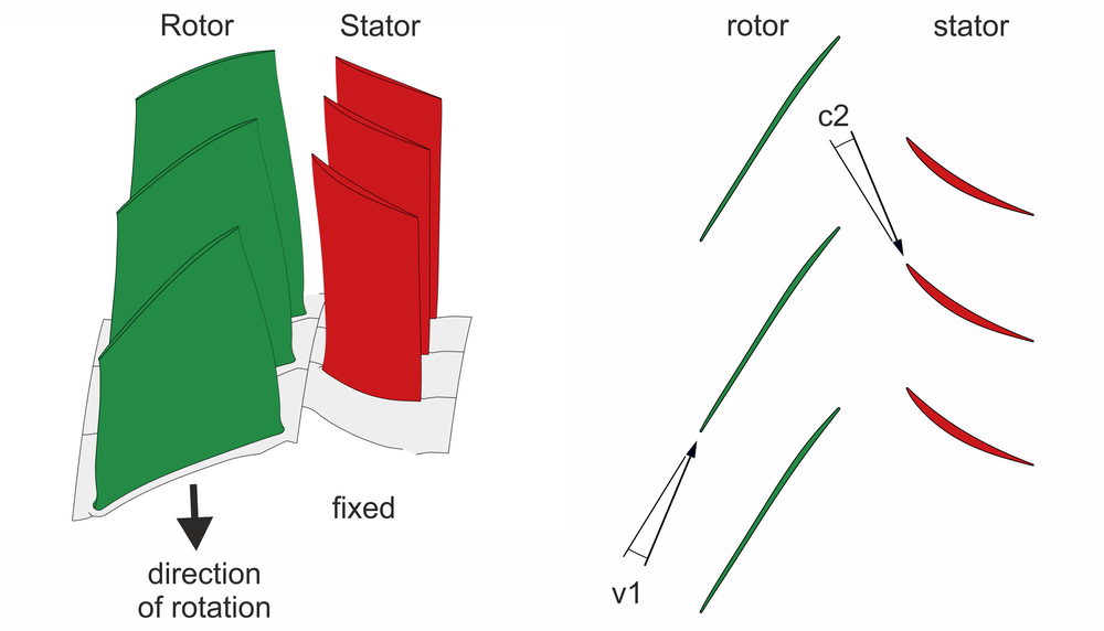
Figure 1 (left hand side) shows a typical compressor stage. It consists of a rotating (rotor) and a stationary blade row (stator). A compressor usually consists of several stages. The shape of the blades and the resulting flow around them is similar to that of aircraft wings. Figure 1 (right hand side) shows the flow angles in a circumferential section of the stage. The angles of attack at the rotor (v1) and stator (c2) are particularly significant for the flow. In contrast to aircrafts, the flow in the compressor is used to increase the pressure level and not to generate lift. The compressor is designed to work in different operating states depending on requirements.
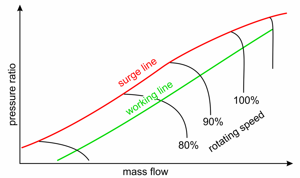
The operating state of the compressor is characterized by both mass flow and pressure ratio parameters. The mass flow indicates how much air mass flows through the engine in one second and the pressure ratio shows the pressure increase between compressor inlet and outlet. Possible operating conditions are shown in the so-called compressor map (Figure 2). The compressor map shows the pressure ratio against the mass flow.
The speed of the rotors as well as the throttle position are used to modify the operating state. If both parameters are kept constant, the compressor remains at an operating point in the compressor map. At a fixed rotation speed, the operating point stays on the respective speed line. The higher the rotating speed, the more air accumulates in the compressor and the higher the pressure level.
If the rotating speed is kept constant and only the throttle position is modified, the operating point shifts along the speed line. When throttling, air is accumulated more intensely: the mass flow decreases, but the pressure ratio and the efficiency increase.
At the same time however, the angle of attack of the flow on the blades increases. As with aircraft, the angle of attack cannot be increased arbitrarily, because flow separation might occur. In compressors, flow separation leads to an unstable flow condition. The stability limit is defined by the surge line in the compressor map (Figure 2). When the surge line is crossed, various unstable phenomena might occur. One of these is the so-called surge.
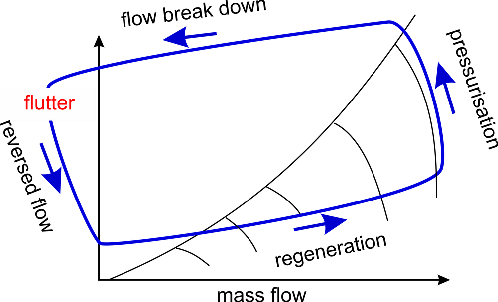
In the case of a surge, the flow stalling at the blades means that the accumulation of air downstream of the compressor can no longer be sustained. The accumulated air discharges in the opposite direction and flows backwards through the compressor. When the pressure level behind the compressor has dropped sufficiently, the flow reattaches on the blades and the pressurization starts over again. If the throttle position is not modified, the pressurization, break down, reversed flow and flow regeneration process is repeated periodically. Typical surge frequencies are around 10Hz, meaning that the process occurs ten times per second. This phenomenon might induce the flutter of the blade row. Figure 4 shows a numerical simulation of the surge process. The mass flow is shown on the top, left hand side. The pressure is shown on the top, right hand side and bottom. The video shows the four typical phases of the surge cycle in which the pressurization and discharge of the accumulated pressure downstream the compressor are periodically repeated.

Flutter is a self-excited vibration phenomenon in which the blade vibration amplitude might increase exponentially and cause blade failure. The flutter phenomenon highly depends on the basic flow. This basic flow is much more complex at surge than at normal operating conditions, which makes the prediction of a flutter onset and behavior particularly challenging.
Figure 3 shows the course of a typical surge cycle in the compressor map. During surge, the basic flow changes continuously with a relatively high frequency. During the cycle, various flow states with complex flow conditions such as flow separation, shocks and reversed flow areas occur.
In flight, a margin is defined and prescribed in order to guarantee safe operation of the compressor and to avoid surge line crossings. However, this margin prevents the compressor from operating in the area of maximum efficiency. As a consequence, the full potential of the compressor is never achieved. The aim of the current research is to improve the understanding of the system behavior during surge, to predict it and, in the best case, to be able to control it. For this purpose, experimental and numerical prediction methods are constantly being developed. At the Institute of Aeroelasticity, these predictions contribute to evaluate blade structural loading and to prevent blade row damage during the experiments.
Christoph Reiber, DLR-Institute of Aeroelasticity, Department: Aeroelastic Experiments