Realistic conceptual design loads in the early phase of the overall aircraft design for the mass estimation of fuselage and wing play an important role in the overall aircraft assessment for new aircraft configurations and propulsion technologies. The empirical handbook methods for mass estimation of wings and fuselage, which are based on existing typical aircraft configurations, are no longer fully applicable. The use of analytical methods with higher fidelity in conceptual design is necessary to be able to adequately reflect the effects of new configurations and technologies.
Overall aircraft design
An overall aircraft design is a multidisciplinary process considering various disciplines such as flight mission, flight physics, aerodynamics, mass distribution, structural sizing (fuselage, wings, control surfaces, landing gear), propulsion, systems and other relevant disciplines. For classic aircraft configurations, handbook methods and/or semi-/empirical methods in the early phase of aircraft design are sufficient to develop the initial configuration. Due to novel configurations with, for example, high aspect ratio wings or folding wing tips as well as new propulsion technologies with hydrogen, battery, fuel cells or distributed propulsion, these classical methods no longer offer sufficient detail to map the decisive aspects of modern aircraft configurations. As part of the EXACT project ([1], [2]), a process for overall aircraft design and evaluation was developed.
Loads in conceptual design
The conceptual loads are calculated using the LOADzero and LGLOADzero tools. LOADzero is a tool for calculating flight loads. Certification-relevant manoeuvre and gust loads are used for the conceptual design. These include manoeuvres with 2.5g and -1g at cruising altitude as well as additional load factors for gusts according to Pratt [3]. The selection of the load cases considered is based, for instance, on the certification regulations, e.g. CS25 [4].
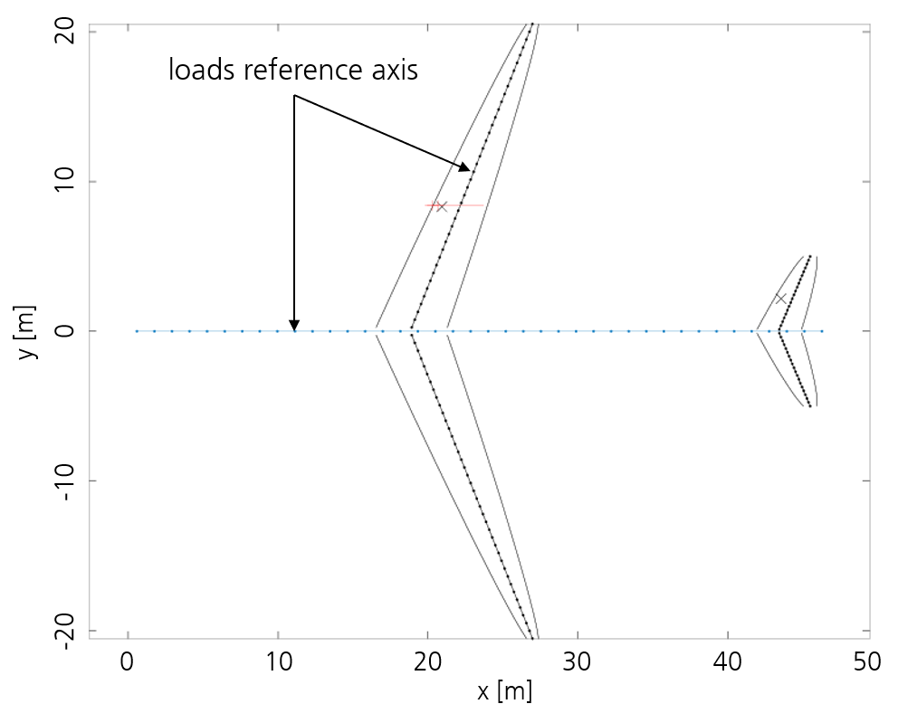
From the CPACS data set, which represents the database for the aircraft configuration [5], information on wing geometry, fuselage length and masses is read in order to build a mass model and the load reference axes of the wing and fuselage. Figure 1 shows an example of a simplified geometry of wings and fuselage.
Based on design mass cases, for example maximum take-off weight, a trim analysis is carried out to calculate the lift and downforce of the wing and tailplane. The lift distribution can be elliptical, trapezoidal or according to Schrenk [6], a combination of the previous distributions. Based on the load case parameter and assuming a rigid wing, local accelerations and subsequently the inertial forces are calculated. As a result, section and nodal loads are provided along the load reference axes.
LGLOADzero is used to calculate maximum static landing and ground loads. The selection of the load cases considered is also based on the certification regulations. Information on design mass cases, the corresponding front and rear centre of gravity positions, the landing gear and geometric constraints (e.g. ground clearance) are used. Among the landing gear information, assumptions are made for landing gear-specific components (e.g. for shock efficiency, damping coefficients). Section and nodal loads along the load reference axes defined in LOADzero are also provided here.
Example: Evaluation of loads of an aircraft with hydrogen system
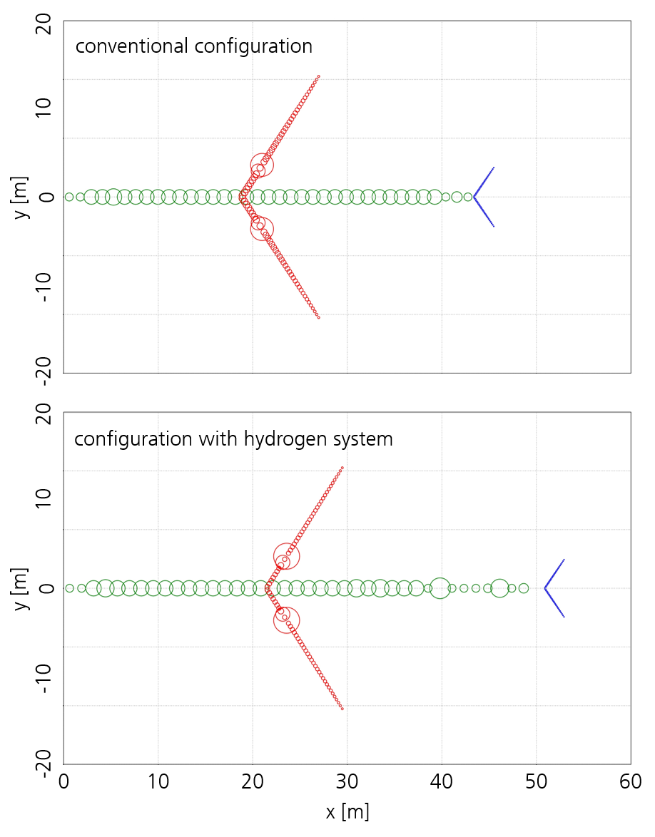
Figure 3: Illustration of mass model for maximum take-off weight of turbofan configurations with and without hydrogen system
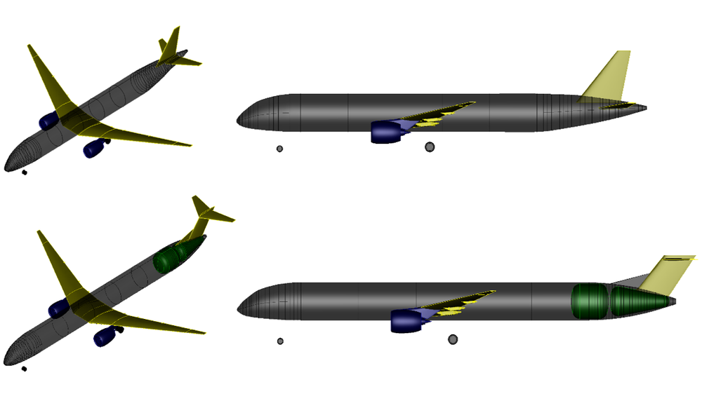
An example of a novel configuration with a hydrogen system and direct hydrogen combustion is shown in Figure 1. In addition to an extended fuselage, the integration of a hydrogen tank mainly leads to a modified mass model of the configuration. The mass models for the maximum take-off weight are shown in Figure 3. On the one hand, heavy masses (hydrogen tank and associated systems) are positioned in the rear of the fuselage. These system masses comprise approximately 4700kg, excluding liquid hydrogen. Secondly, the absence of fuel results in a so-called "dry" wing. This means that the relieving mass forces of the fuel in the wing, which counteract the aerodynamic forces, are absent. In Table 1 provides a few key data of the two configurations.
Turbofan SynFuel / Fossil
Turbofan Mild-Hybrid LH2
Empty operating mass [t]
47.70
55.30
Maximum take-off mass [t]
80.03
82.58
Fuel mass [t]
8.10
2.25
Hydrogen system [t]
-
4.71
Fuselage length [m]
46.85
50.57
Span [m]
42.00
42.00
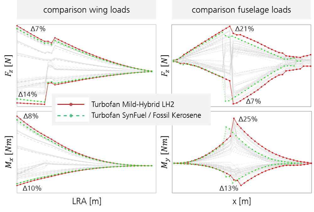
In Figure 4 the comparison of the wing and fuselage loads of the configurations with and without a hydrogen system is shown. The positive and negative maximum loads of the configurations are highlighted in colour. The comparison of the wing loads shows a 7% and 14% increase in the Fz force of the hydrogen configuration at the wing root in the positive and negative range, respectively. A view on the bending moment Mx shows an increase of around 8% and 10% for the hydrogen configuration at the wing root in both the positive and negative maximum values. This is the result of the aforementioned effect of the "dry" wing. The local increase in force of the landing gear has no significant influence on the bending root moment.
Figure 4: Comparison of the wing (left) and fuselage (right) loads
A comparison of the fuselage loads shows increases of 21% and 25% in the positive range and 7% and 13% in the negative range for both the maximum Fz force and the My moment, respectively. In the fuselage area behind the wing, shifts in the curves towards larger values can be observed. One reason for this is the extended fuselage, which increases the lever arm for the moment. Another reason is the change in the mass distribution due to the heavy hydrogen system at the rear, resulting in greater Fz forces.
The analysis of the loads shows that novel aircraft concepts and propulsion technologies have a significant influence on the loads on the aircraft. In addition, future wings with greater span and aspect ratio or even wings without fuel must be examined more closely in individual cases with regard to their aeroelastic behaviour.
[6] Schrenk, O., “Ein einfaches Näherungsverfahren zur Ermittlung von Auftriebsverteilungen längs der Tragflügelspannweite”, Luftwissen; Bd. 7, Nr. 4, April 1940, pp.118–120.
Recommended reading
Hecken, Tobias and Petsch, Michael and Zerbst, David (2023) Structural wing and fuselage design. EXACT Public Symposium: Which Ways Lead Towards Sustainable Aviation by 2040?, 04.09.2023, Online. https://elib.dlr.de/198966/
Hecken, Tobias and Balack, Philip and Petsch, Michael and Zerbst, David (2022) Conceptual Loads Assessment of Aircraft with Fuselage Integrated Liquid Hydrogen Tank. Deutscher Luft- und Raumfahrtkongress 2022, 27.-29. Okt. 2022, Dresden, Deutschland. https://elib.dlr.de/189171/
Zerbst, David and Hecken, Tobias and Balack, Philip and Freund, Sebastian and Werthen, Edgar and Dähne, Sascha and Hühne, Christian (2022) Preliminary Design of Composite Wings using Beam-based Structural Models. DLRK 2022, Dresden. https://elib.dlr.de/188725/
Petsch, Michael and Kohlgrüber, Dieter and Leon Munoz, Christian and Hecken, Tobias and Balack, Philip and Atanasov, Georgi and Silberhorn, Daniel and Zerbst, David (2022) Analytical fuselage structure mass estimation using the PANDORA framework. DLRK 2022, 27.-29. Sept. 2022, Dresden, Deutschland. https://elib.dlr.de/192843/