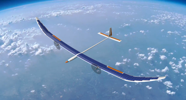
The High Altitude Platform (HAP) is a very light weight, high altitude and long endurance aircraft (HALE) designed to stay airborne and hold position for several days at an altitude between FL450 and FL800 (≈14 to 24 km, above normal air traffic). Carrying optical measurement equipment (up to 5.0 kg), this allows scientists to make observations of the earth continuously for a long period of time. This is an advantage compared to satellites, which typically pass the same spot only every couple of days and fly much higher, leading e.g. to a lower optical resolution. The ability to take-off and land allows to re-configure and relocate the aircraft for new and different missions. In addition, purchase and operation costs of an aircraft are expected to be much lower compared to those of a satellite, including the infrastructure (airfield vs. spaceport). An illustration of the HAP configuration, currently under development at the DLR, is shown in Figure 1.
Why is aeroelasticity important?
The aircraft flies very slow (VEAS = 9.0 … 11.0 m/s) but is highly efficient in terms of propulsion and aerodynamic performance (aspect ratio = 20) and is powered by solar electric energy. This requires a design which offers large areas for the installation of solar panels (wing span = 27.0 m) and is very light weight (mdesign = 136 kg) at the same time. Considering that the aircraft is very light, slender and flexible, there is a strong interaction of aeroelasticity with nearly all aspects of the aircraft design so that this aircraft can be called “highly elastic”. However, this doesn't mean extreme geometric deformations, for example the wing tip deflection in horizontal level flight at normal operational speed is ≈5 … 6 % of the half-wing span.
How to include aeroelasticity in the aircraft design process?
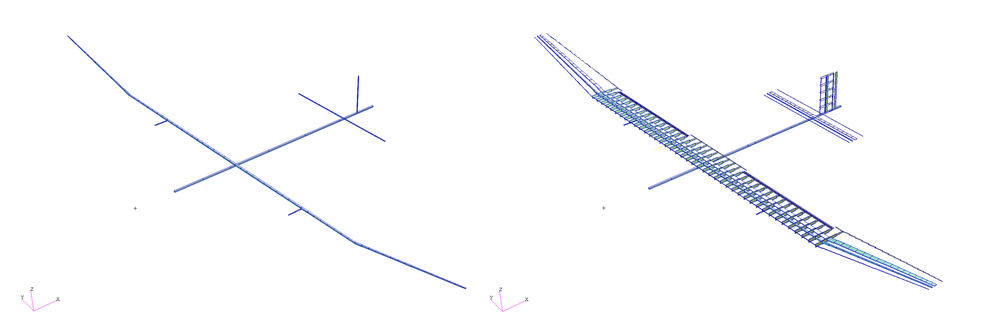
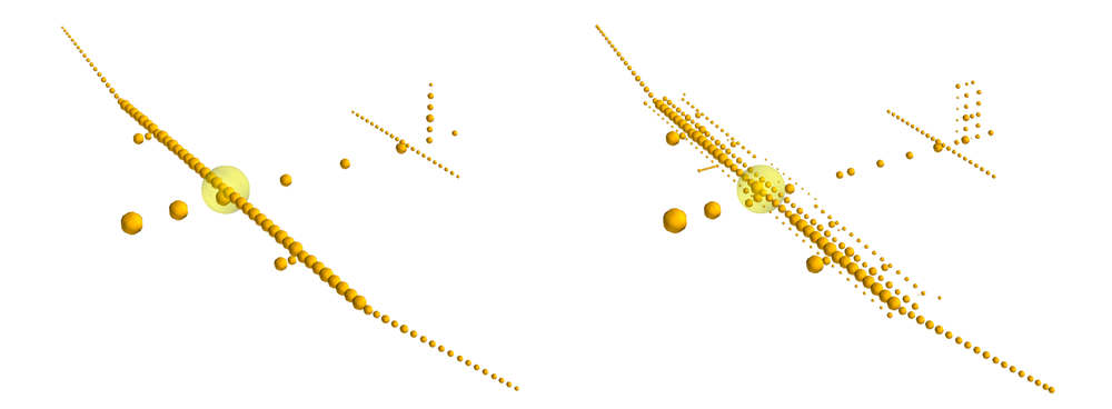
To ensure a safe and reliable aircraft design, aeroelastic analyses have been prepared already during the preliminary design phase of the aircraft. During the progress of the project, the aircraft design has evolved and matured. On the one hand, more analyses have been performed, leading to a better knowledge and understanding of the configurations. On the other hand, the underlying data has improved, e.g. estimates of system masses have been replaced by the actual masses of the real components. Finally, the design became more detailed from a construction point of view (detailed CAD design of parts, drawings, manufacturing of prototypes, etc.), leading to more reliable mass and stiffness properties. This evolution from a preliminary to a more detailed design is reflected in the aeroelastic modeling, as shown in Figures 2 and 3 for the structural and the mass models.
Figure 2: MSC.Nastran beam models, preliminary and more detailed model
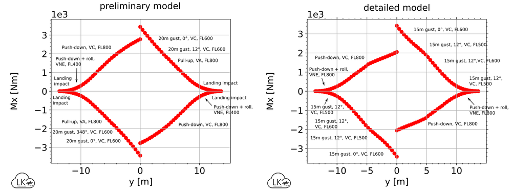
For the sizing of the aircraft, a set of load cases is considered, including maneuver, gust, landing and propulsion loads. The resulting loads are integrated at so-called monitoring stations, for example along the wing, to create section loads. Figure 4 shows the envelope of the bending moment Mx along the wing span and each dot marks the highest positive or negative bending moment at one monitoring station. Comparing left- and right-hand side, the bending moments are symmetrical with swapped signs. Comparing the preliminary with the detailed model, the results are very similar in both shape and amplitude, although many details are added on the modeling side. So by including aeroelasticity very early in the design phase, we decreased the risk of (costly) changes in the design at a later stage and increased our confidence in the aircraft.
Manufacturing will start in 2023, followed by a detailed testing phase to validate and/or update the simulation models. The first flight is planned for 2024 and will take place at low altitudes first and in a dedicated, restricted airspace, followed by a detailed flight test campaign.
DLR project HAP - institutes and facilities involved
Institute of Flight Systems (project mamagement)
Institute of Aeroelasticity
Institute of Aerodynamics and Flow Technology
The German Remote Sensing Data Center
Institute of Electrified Aero Engines
Institute of Composite Structures and Adaptive Systems
Arne Voss, Department Loads Analysis and Design, DLR Institute of Aeroelasticity
Arne Voß studied aerospace engineering at the Hamburg University of Applied Sciences and holds a PhD from the Technical University of Berlin. Since 2014, he works at the DLR Institute of Aeroelasticity in Göttingen, Germany. Currently, he is in charge of the aeroelastic design and analysis of a High Altitude Platform, the loads analysis and structural sizing of a Future Fighter Demonstrator and collaborates with TU Berlin to build the very flexible demonstrator “TUFlex”.