To increase the aerodynamic efficiency of the future generation of short- and medium-range aircraft, the aspect ratio (ratio of wingspan to wing area) is continuously increased. From an aeroelastic point of view, this means that the wings become more slender and more flexible. As a result, the structural load at the transition between the wing and fuselage is increasing due to the larger lever arm. In addition to the structural dynamic properties, the aerodynamic design of such a wing also plays an important role in the modeling of dynamic loads. In order to predict these loads in detail and in a time-efficient manner, an adequate model depth must be selected for the aeroelastic simulation.
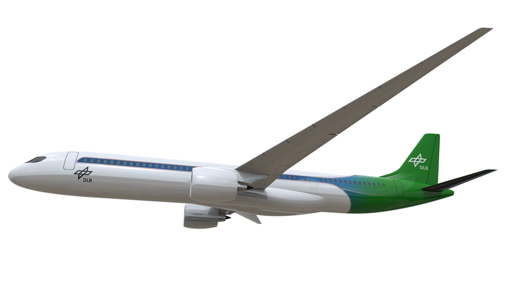
Current methods for calculating dynamic loads have been limited to the use of linearized models, such as aerodynamic panel methods or linearized CFD-methods (computational fluid dynamics). These offer fast evaluation times suitable for structural optimization, controller synthesis or evaluation of new designs. However, the assumption of linearity cannot be confirmed for all flight cases, which leads to uncertainties and means that the structure may not be optimally utilized in terms of dimensioning. Using the DLR-F25 aircraft configuration, shown in Figure 1, the EU-project UP-Wing aims to investigate the effects of considering nonlinearities and active gust load alleviation on structural design. In terms of modeling, two questions have to be answered: What types of nonlinearities should be simulated? And how can the complex CFD simulation be accelerated for use in structural optimization?
What types of non-linearities are relevant in load analysis?
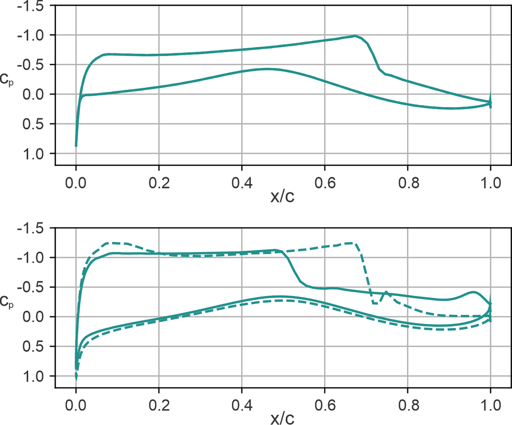
With regard to dynamic gust loads on aircraft, the focus is primarily on two different types of amplitude-dependent aerodynamic nonlinearities [2]. The first of these is shock-induced flow separation. This occurs at high angles of attack during a gust encounter. The flow can no longer follow the contour of the profile due to the large increase in pressure, resulting in a reverse flow behind the compression shock, which then moves forward on the wing. This is shown in Figure 2. By taking this type of nonlinearity into account, the loads on the wing root can be significantly reduced, particularly in the range relevant to cruise flight.
Figure 2: Local pressure of an airfoil section
Top: with shock and without gust; Bottom: during the gust with flow separation. Dotted line: results of a linear simulation; Solid line: results of a non-linear simulation.
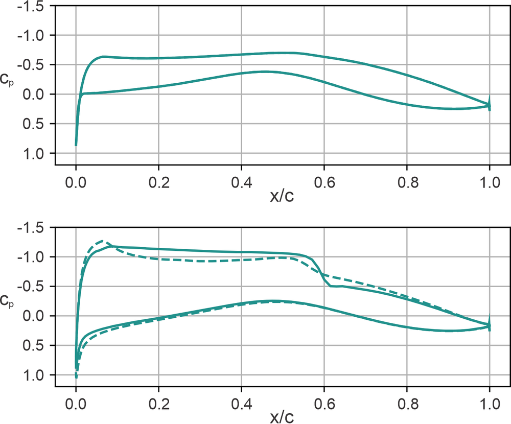
The second type of nonlinearity is found just below the critical Mach number. This is the flight speed at which the flow on the upper side of the wing locally reaches supersonic speed. The additional gust speed further accelerates the flow on the upper side of the profile, so that it reaches supersonic speed and a compression shock emerges. This leads to a nonlinear increase in lift, as plotted in Figure 3.
Figure 3: Local pressure of an airfoil section
Top: without shock and without gust; Bottom: during the gust with emerging shock. Dotted line: results of a linear simulation; Solid line: results of a non-linear simulation
To physically capture these two types of nonlinearities, a CFD simulation in the time domain is required. Since these are numerically very complex and time-consuming, the second question arises:
How can the complex CFD simulation be accelerated for use in structural optimization?
Even though the performance of modern processors has steadily increased in recent decades and the DLR has two high-performance clusters at its disposal, CFD simulations in the time domain for several dozen to hundreds of load cases in an iterative structural optimization process are still too time-consuming. Therefore accuracy and computational costs have to be balanced carefully.
To determine the loads on an aircraft, the aircraft must be considered as a whole,including the wings, fuselage, and tail. This is necessary in order to correctly capture the flight mechanical properties, as these have a significant influence on the loads on the wings. However, not every component of the aircraft needs to be modeled with the same level of accuracy. Only the wing must be considered with a viscous boundary layer, as this is essential for modeling the nonlinearities described above. The surface of the fuselage and tail, on the other hand, can be modeled as frictionless in a first approximation. This reduces complexity and can significantly reduce simulation time. Together with the use of symmetries, the effort required for such a simulation can be reduced to an acceptable time frame without any relevant loss of accuracy [3].
Controlled loads on the DLR-F25
So-called functional mock-up units (FMUs) can be used to integrate flight controllers, gust load mitigation controllers, or even control surface actuators. These are small, standalone programs that allow the modeling accuracy to be increased at the system level and enable the exchange between different partners. In this case, a controller from TU Berlin was integrated into the in-house simulation environment UltraFLoads [4] with the help of an FMU. The feedback controller aims to reduce loads during flight. Depending on the effectiveness of such a controller, the mass of the wing structure can be reduced, which has a direct impact on the aircraft's fuel consumption. With the help of CFD simulation, the effects of nonlinear behavior on the effectiveness of the controller and the resulting structural weight can be investigated.
Figure 4: Comparison of local lift coefficient along the wing during a gust encounter for the controlled (closed loop) and uncontrolled (open loop) aircraft (linear and non-linear)
Figure 4 shows the comparison between linear and nonlinear simulation, with and without controller. These preliminary results show the local lift coefficient on the wing during a gust encounter. Here, a clear difference between the linear and nonlinear results can be seen, which is the effect of flow separation. In addition to this non-linear effect, the effect of the controlled aileron deflection can also be seen particularly clearly in the linear simulations.
Acknowledgement
The project Ultra Performance Wing (UP Wing, project number: 101101974) is supported by the Clean Aviation Joint Undertaking and its members.
Disclaimer
Co-Funded by the European Union. Views and opinions expressed are however those of the author(s) only and do not necessarily reflect those of the European Union or Clean Aviation Joint Undertaking. Neither the European Union nor the granting authority can be held responsible for them.