While the long-term goal is to make Europe’s aviation climate-neutral until the year 2050, the reduction of fuel consumption and thus CO2 emission is a major objective. To increase the efficiency and overall performance, larger fan diameters and higher bypass ratios are consistent trends. An associated technical requirement is lightweight design. The solutions are lighter materials like aluminum or composite (carbon-fiber reinforced plastics, abbr. CFRP) and hollow blades.These lightweight constructions require new methods to safely analyze the aeroelastic stability.
The Evolution of Turbofan Designs
Classical turbofan engine use titanium, which is a light, very strong and robust material, but expensive and not easy to machine or repair. For structural integrity, the fan blades do not need to be a solid metal block. Improvements in manufacturing techniques allow for more complex geometrical shapes as well as a hollow design (or sandwich construction).
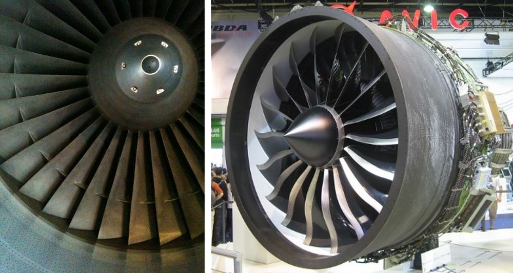
Fig. 2: Different generations of turbofan engines.
The number of blades reduced over the years. The newer generation of fans are also called wide-chord fans because of their appearance with significantly longer chordlength than the older generations.
Left: Fan blade of a Rolls-Royce RB211, introduced in 1969, right: General Electric GEnx, introduced in 2007
Credit:
David Fisher via Flickr.com Copyright CC BY 2.0, Aan'Allein via Flickr.com Copyright CC BY-NC 2.0
Flutter or Aeroelastic Stability of the Blades
Flutter is a self-excited vibration of an elastic structure in a fluid flow. The phenomenon occurs when the motions of the structure cause such aerodynamic forces that the vibration amplitude isn’t damped and increases exponentially over time. This exponential nature of the phenomenon leads to rapid destruction and thus, flutter has to be avoided at all costs.
To do so, either structural damping or aerodynamic damping can be used. Modern fans and compressors have a very low structural damping (due to design aspects e.g. blade-integrated disks, abbr. blisk). Structural damping counteracts any aerodynamic excitation forces and is therefore a conservative margin. In early turbofan designs, the blades where equipped with mechanical dampers at approximately half the radius (Fig. 2, left side). These dampers, sometimes called snubber, were used to suppress vibrations of the blades, which could not be predicted by the design methods. Within the last decades, thanks to the increasing high-performance computing power and increasing accuracy of computational fluid dynamics (abbr. CFD) and computational structural mechanics (abbr. CSM), engineers were able to examine blade vibrations in more detail and eliminate designs which would lead to high vibration amplitudes. As a consequence, the snubbers are not needed anymore, which also improves the efficiency because the air flow is less disturbed.
Another aspect considered to damp blade vibration is the accurate prediction the aerodynamic damping in early design phases in order to exclude aerodynamic excitation by blade vibrations. In the past, simulations of such blade vibrations were performed at the blade natural frequency and the vibration motions were assumed to be in the modeshape associated to this natural frequency (deflection pattern that represents the relative displacement of all parts of a structure for that particular mode).
Flutter Analysis of Lightweight Engine Blades
With the consistent lightweight design of aero engine blades, the so-called mass ratio between structural components and the air flowing around the blades drops. At lower mass ratios, the blades are more susceptible to even small fluctuations in the unsteady aerodynamic forces. Below a certain level of mass ratio, structural vibrations and the aerodynamic forces can influence each other so strongly, that the vibrations do not occur at the natural frequency and the related modeshape anymore. The phenomenon is called coupled-mode flutter. It is well known from aircraft wing structures already and has been studied intensively over the decades.
Most current aero engines are assessed by the classical method which has been established for decades. The flutter-free operating range can be predicted with good confidence during the design phase. The mass ratio of these designs is still above a threshold where coupled-mode flutter becomes a concern.
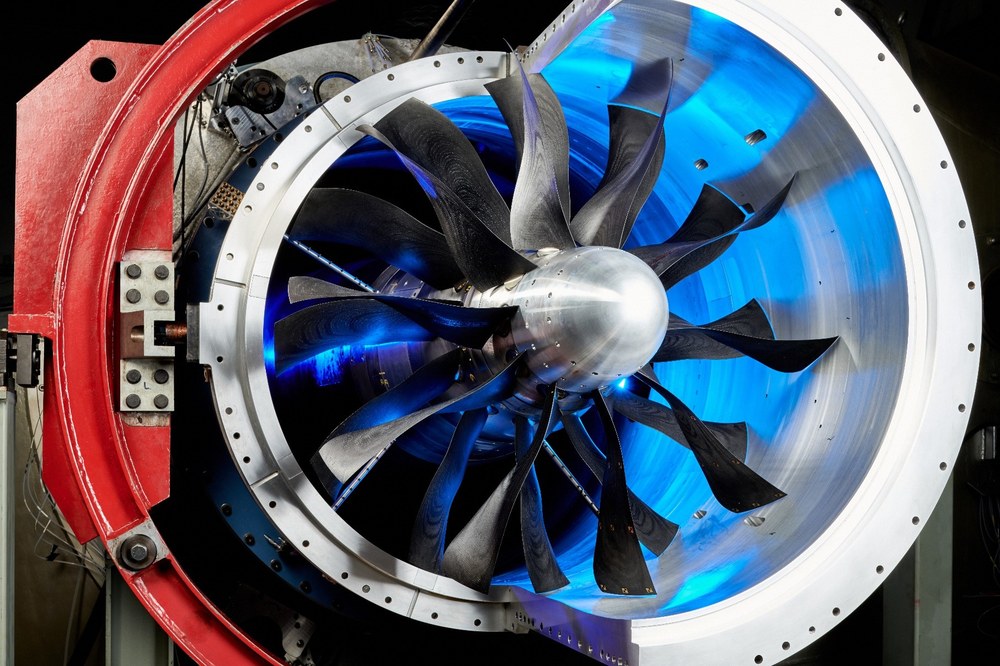
Currently, a two-stage counter-rotating fan with a very low mass ratio is at the testbed of DLR in Cologne (Fig. 1). Using only the classical analysis method which leaves out the coupling effects, the flutter-free operating range is significantly overestimated (Fig. 3).
Although the mass ratio of the CRISPmulti rotor is far below that of current aero engine designs, the results emphasize that coupled-mode flutter will have to be respected for future generations of aero engine, especially fan blades.
Fig. 3: Compressor map of the CRISPmulti with flutter boundary
ADP means Aerodynamic Design Point, the operating condition with the highest aerodynamic efficiency, which is typically the cruise flight thrust setting.
Previously, the coupled-mode flutter phenomenon was not assessed in the design phase. At the DLR-Institute of Aeroelasticity, the expertise and developed numerical methods used to examine coupled-mode flutter in wing designs are transferred to aeroelastic analysis of aero engine blades. The method is adapted and refined for the usage on turbomachinery-specific numerical setups. Now coupled-mode flutter analysis can be included into the design phase of future aero engines.