
TRON – Testbed for Robotic Optical Navigation


Motivation
Future exploration missions will require advanced capabilities such as precise and safe landings on planetary bodies or rendezvous and docking operations. Many of these missions will take place in the Earth and lunar environment as well as on distant targets such as Mars or the icy moons of Jupiter and Saturn. Reliable operations require both autonomy of the spacecraft and the use of the target body as a navigation reference. The use of optical navigation methods and technologies is considered promising for the realisation of this concept. Unsurprisingly, these modern approaches require a significantly higher level of detail about the mission target to be processed on board. On the one hand, this comes from data from current mapping missions, from which, for example, catalogues with georeferenced landmarks can be derived. Such a priori information is supplemented by measurements taken during the course of the mission, which are used, for example, for comparison with an on-board landmark catalogue or to assess the nature of the landing area. All of these applications result in the need for significantly improved computing capacity, new types of optical sensors and complex algorithms for processing the data supplied by them.
GNC systems that fulfil such requirements are the focus of many development projects, one example being the DLR project ATON. What all projects have in common is the need for intensive testing. TRON was developed and implemented for this purpose.
TRON Introduction
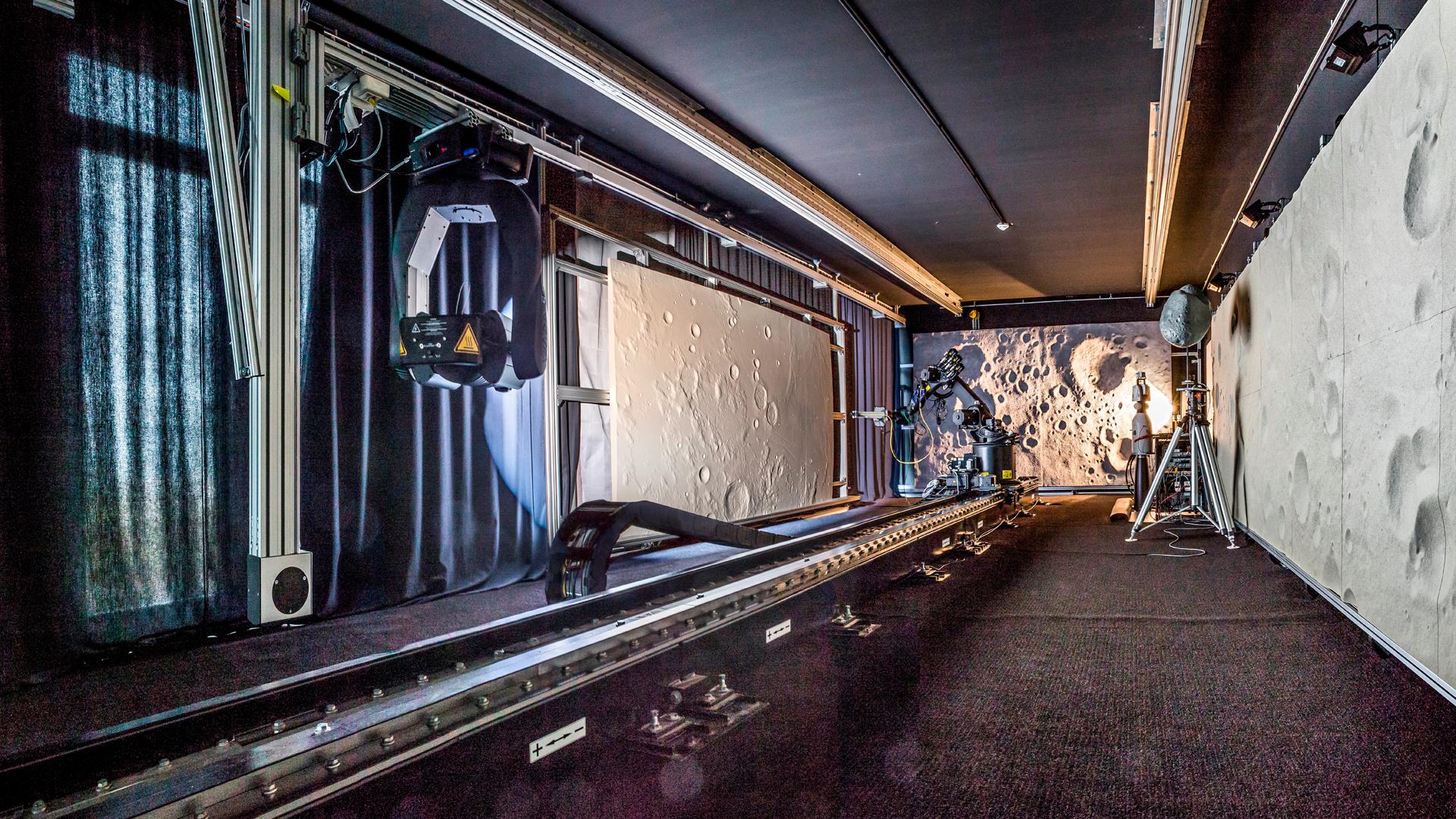
TRON is a Hardware-in-the-Loop Test (HiLT) test facility with the aim of supporting the development and testing of optical navigation technologies. Accordingly, TRON offers a laboratory environment to qualify breadboards up to TRL (Technology Readiness Level) 4 and to qualify flight models up to TRL 6. Typical hardware that can be tested in TRON are passive and active optical sensors such as cameras or flash lidars.
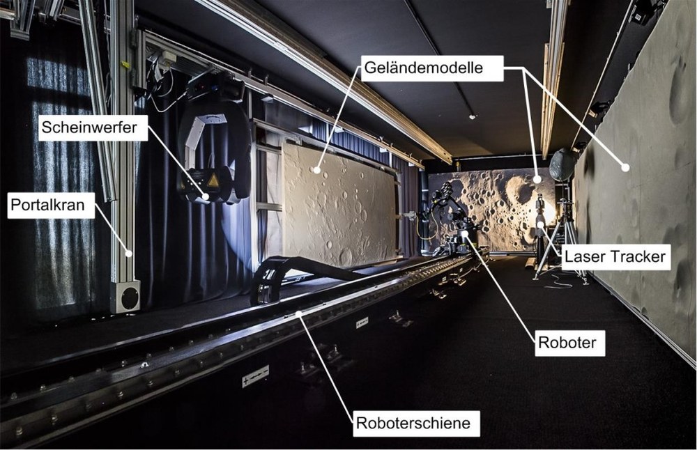
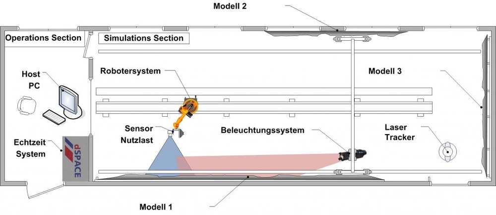
The main components of the laboratory are a robot for the dynamic positioning of the hardware to be tested, a dynamic lighting system, laser measuring devices for high-precision reference data and a dSPACE real-time system for controlling the tests and synchronizing the reference data with the sensor data. Different tests place different demands on the test environment. With the help of user-defined extensions such as terrain models, the laboratory environment can be adapted accordingly.
In its current version, TRON is equipped with three terrain models of different scales, which together allow the simulation of a complete lunar landing trajectory. Such a scenario begins in a parking orbit and ends with the descent during the last one to two kilometers to the landing site. In addition, a large number of bodies with simple shapes are available for use. For active sensors such as flash lidars, TRON is equipped with laser protection curtains that allow the operation of class 4 lasers.
Dynamic positioning
Dynamic positioning is performed by a robot system. Its maximum payload is around 16 kg on the robot hand, supplemented by a further 24 kg distributed over the robot arm and the robot base. The static repeat accuracy is 0.1 mm, the maximum speed that can be achieved is around 1.5 m/s. The robot can be controlled manually, via scripts or with the help of the dSPACE system via a real-time interface.
Terrain models
Three terrain models are currently installed in TRON.
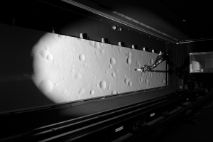
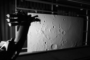
Model 1 has a size of 9.80 m x 1.96 m. Its dynamic range, the difference between the lowest and highest point in the terrain, is around 6.2 cm. The model was produced with a milling accuracy of 1 mm. The necessary reference data was generated using software that creates surfaces representative of the moon. According to certain criteria, such as the distribution of craters, the lunar surface is self-similar over a certain scale range. This allows the use of different scales during the simulations. As an example, a simulation run along model 1 is used, in which the distance to the surface is varied between 0.5m and 3m. At a simulation scale of 1:10000, this allows the spacecraft's motion dynamics of 100 km along the model and flight altitudes between 5 km and 30 km to be represented.
So far, the model has been used for testing the breadboard of the ESA Lunar Lander project and for the DLR ATON project. Both projects worked with scales between 1:10,000 and 1:50,000 for the simulation of sections of the Descent Orbit and the Powered Descent.
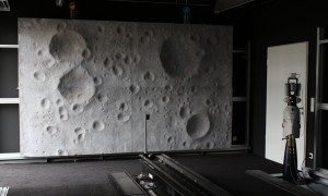
Model 2 has a size of 3.92 m x 1.96 m. It represents a part of the moon on a scale of 1:125000, its dynamic range is 20 cm. The model was produced with a milling accuracy of 1 mm. The reference data comes from the measurements of the Japanese Kaguya mission. With this model, park orbits and parts of the descent orbit can be simulated well. Unlike Model 1, Model 2 has the natural curvature of the moon; it has so far been used to simulate parts of the descent orbit to support the development of the crater navigation software in the DLR ATON project.
Terrain model 2 shows a section of the moon at a scale of 1:125000. The real size is 500 km x 250 km.
Model 3 has a size of 4.20 m x 2.20 m, its dynamic range is 26 cm. The reference data for the model was produced by DLR by first modeling the surface manually and then transferring it to a digital elevation model. The surface was then milled, finished by hand, colored and finally provided with stone structures. The result is a high level of detail. This model is ideal for simulating the approach phase to the landing site. So far it has been used for camera tests in the ATON project and for flash lidar tests in FOSTERNAV.
In addition to the surface of the moon, the model is also suitable for other applications, e.g. an asteroid scenario.
Other test objects
In addition to a lunar scenario, the TRON laboratory offers further test objects, e.g. a model of the asteroid 433 Eros on a scale of 1:34000. The asteroid can be rotated around its vertical axis.
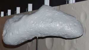
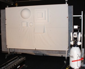
There is also an area measuring 3 m x 2 m that can be placed anywhere in the laboratory. This includes a collection of primitive bodies that can be installed on this surface. This test object was used in various configurations in the FOSTERNAV project.
Optical environment
The optical environment is simulated with the help of a darkening system, materials to reduce reflections and a lighting system.
The blackout system consists of curtains set into the window frame, which seamlessly cover all windows when closed. Reflections are reduced by black carpets, curtains and walls.
The lighting system comprises a gantry crane that can be moved across the entire laboratory area and on which a spotlight that can be rotated in two axes is installed. Together with the gantry crane, the lamp forms a flexible lighting system that can be used to present a variety of lighting situations in the laboratory.
Key activities
- Since 2011: continuous research in the DLR ATON project. Performance of various dynamic tests with overflights over all three moon models.
- 2017: ESA project CECILE (ESA contract number: 4000113067/14/NL/SFe). Movement of a flash lidar relative to a target object.
- 2016 ESA project MILA (ESA contract number: 4000112045/14/NUHB). Movement of a flash lidar relative to a target object.
- 2014 EU FP7 project SINPLEX. Movement of a GNC system relative to lunar model 3 and the Eros asteroid model.
- 2014 EU FP7 project FOSTER²NAV. Movement of a GNC system relative to a target object.
- 2012 ESA project Lunar lander Phase B1. Movement of a camera sensor relative to lunar model 1.