In the pursuit of more efficient aviation, the aerospace industry is moving toward aircraft designs characterized by high-aspect-ratio and highly flexible wings. While these designs offer significant aerodynamic advantages, they may be more prone to present lightly damped modes or even unstable aeroelastic modal coupling. If this occurs, structural stiffening or mass redistribution are conventionally employed to mitigate the resulting structural vibrations or even suppress instabilities. This represents a passive method of achieving damping augmentation. A more appealing approach is the use of active technologies to deflect the aircraft’s control surfaces in such a manner that the oscillations are effectively damped. This concept is known as Active Flutter Suppression (AFS) or active damping augmentation and it is regarded as a more weight-efficient solution. However, transitioning these technologies from theory to commercial reality requires rigorous, safe experimental validation.
The SAFER² demonstrator: a benchmark for active control technologies
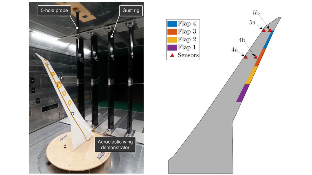
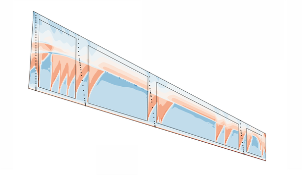
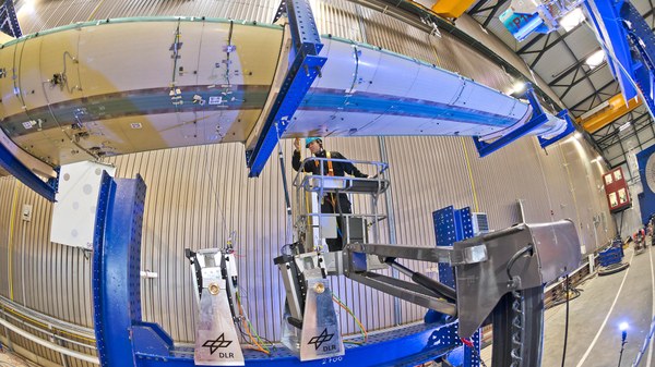
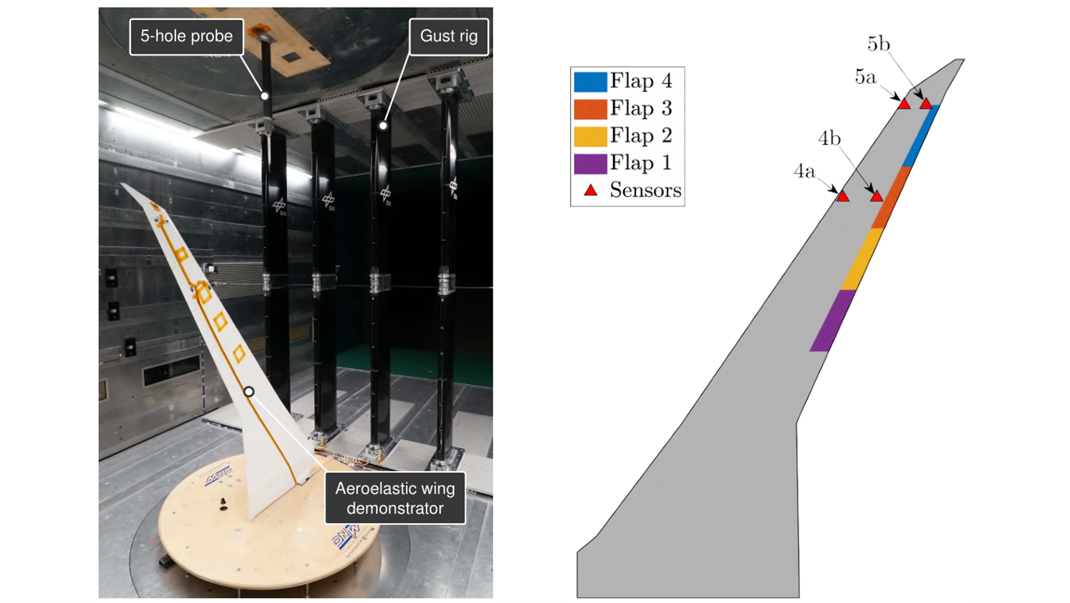
To propel the transition, an experimental demonstration of an active damping augmentation controller was conducted using the SAFER² aeroelastic demonstrator (Sensor and AI Fusion for Enhanced PeRformance and Reliability). This reference model is a high-aspect-ratio swept wing equipped with four trailing-edge flaps and several acceleration sensors used for both model identification and control feedback. The tests took place in the DNW Braunschweig Low-Speed Wind Tunnel (DNW-NWB), capable of wind speeds up to 90 m/s. To further challenge the damping augmentation controller, an ad-hoc gust rig was installed upstream to generate vertical gusts, reproducing the turbulent conditions an aircraft might encounter in flight. Finally, a five-hole pressure probe was mounted on the wind tunnel ceiling to measure the incremental gust angle induced by the gusts. The installation of the wing in the DNW-NWB is shown in Fig. 1 (left). Control surface and sensor locations are depicted in Fig. 1 (right) on the planform of the wing. More information about the demonstrator can be found in [1].
Figure 1: SAFER² wing
Left: Wing with gust generator inside the DNW-NWB, right: Layout of control surfaces and sensors
A Safe Path to Instability: the Saturated Destabilizing/Stabilizing approach
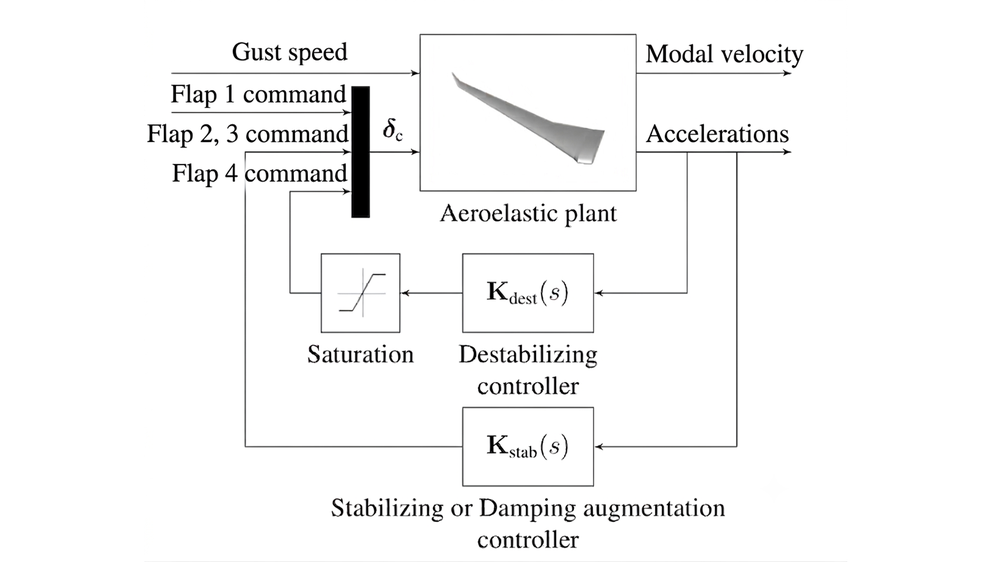
One of the primary hurdles in testing a damping augmentation controller designed to restore stability of a configuration undergoing flutter conditions is the inherent risk: if a stabilizing controller fails during a test on a naturally unstable wing, the resulting divergent response could destroy the model and significantly damage the wind tunnel! To circumvent this, the saturated destabilizing/stabilizing strategy [2] was applied. This method involves three main features and two distinct control loops:
The destabilizing loop: this inner loop commands a specific control surface motion, in this case motion of Flap 4, to artificially reduce the damping of the first wing bending (WB) mode. By adjusting the gain of this specific controller, denoted as “destabilizing gain” it was possible to precisely tune the wing's first WB mode damping from a stable +10% value down to an unstable value of -2%. In summary, this loop represents an “artificial approach” to create an instability.
The saturation block: a crucial innovation in this setup was the inclusion of a saturation block in the destabilizing loop. When the destabilizing gain was tuned to achieve negative damping values, namely unstable conditions, the saturation limited the flap's deflection, forcing the system into a controlled Limit-Cycle Oscillation (LCO) rather than a destructive, divergent response. This allowed for the safe investigation of unstable configurations without the need of traditional "flutter-stopper" mechanisms. This is what made the instability safe and manageable.
The destabilizing loop/damping augmentation loop: with the wing safely "pushed" into instability, the next task was to stabilize it. A stabilizing controller was built using an Ɦ∞ framework aimed at mode attenuation. By reading the wing’s motion via the accelerations delivered by the sensors depicted in Fig. 1 (right), the controller was able to continuously deflect Flap 2 and 3 in a way that the unstable oscillations were suppressed. This is the control loop that restores stability.
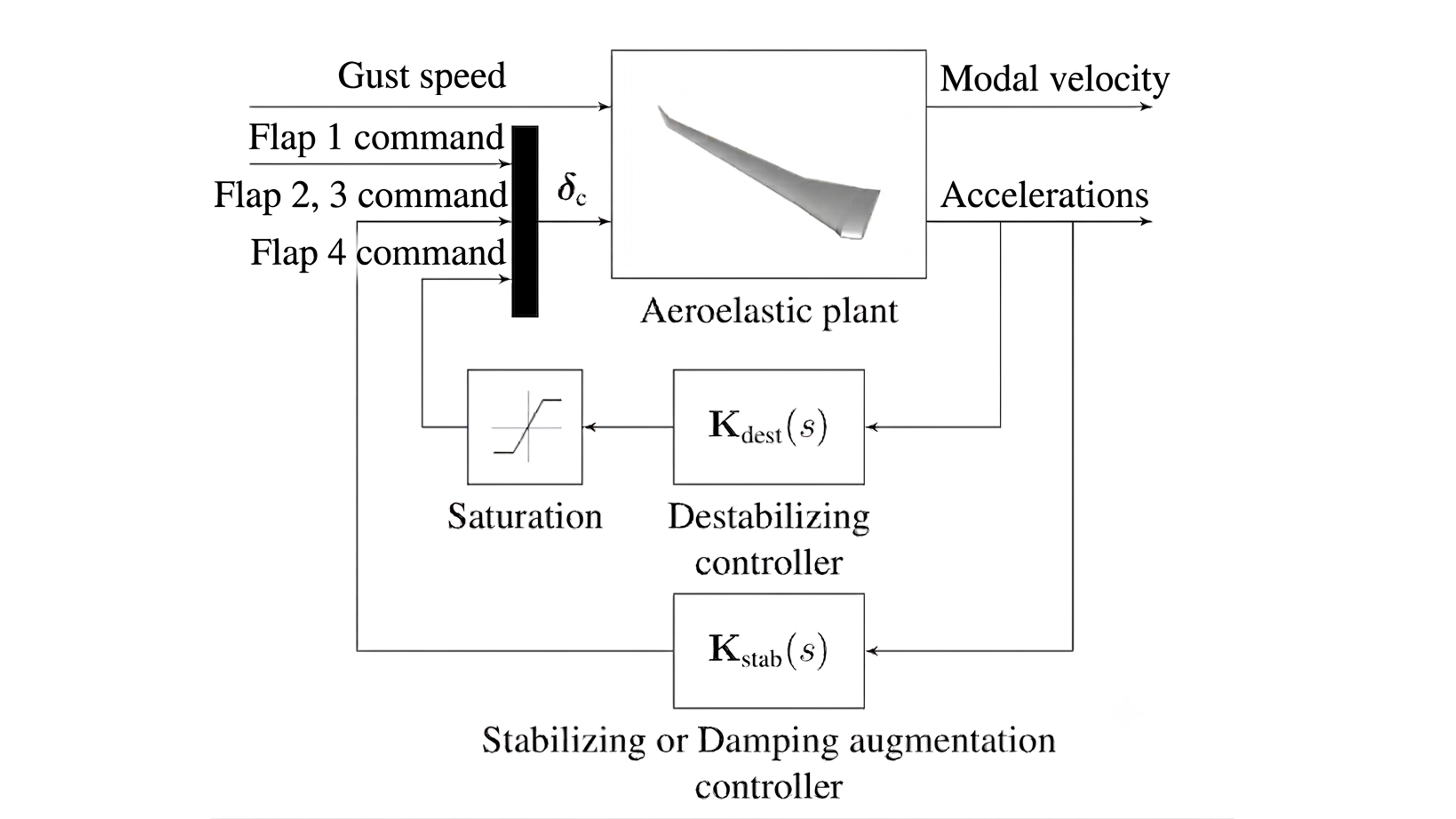
Ultimately, this control architecture (depicted in Fig. 2) made it possible to safely test a damping augmentation controller on an unstable wing configuration.
Figure 2: Illustration of the employed closed-loop architecture for damping augmentation activities
Putting it to the test: case study and monitoring settings
The control algorithms described in the previous section are implemented into an ADwin-Pro II real-time controller which reads the acceleration signals and commands the necessary flap deflections. In this article, we show the results for two primary configurations among the many that were examined:
The Unstable Baseline: The destabilizing controller is active (tuned to a target of -2% damping) while the stabilizing controller remains OFF.
The Controlled Response: The destabilizing controller remains set to -2%, but the stabilizing controller is activated at 1/4 of its full power, a setting we refer to as the SOFT configuration.
Why use 1/4 power? The decision was driven by the need for precise scientific measurement. To quantify exactly how much damping the stabilizing loop adds to the wing, Operational Modal Analysis (OMA) running in real-time was employed [3]. OMA served as an online monitoring tool that analyzed the vibration data from the wing’s accelerometers to identify its modal parameters, such as natural frequency, damping ratios and mode shapes. In this case the identified damping ratios were employed as a performance metric to quantify the achieved damping augmentation. When the stabilizing controller was run at its full power, it was so effective at suppressing vibrations that the wing became nearly static. While this is ideal for flight safety, it created a challenge for data collection as the signal-to-noise ratio became too low for accurate vibration measurements which are then relied upon by the OMA system. By reducing the controller to 1/4 power, the wing remained stable while allowing enough residual vibration for the OMA system to reliably track and validate the damping increase. OMA was also employed to assess the damping loss caused by the destabilizing loop, with the stabilizing controller OFF. However, for this configuration, vibrations were intentionally amplified by the control loop and OMA could identify the modal parameters reliably.
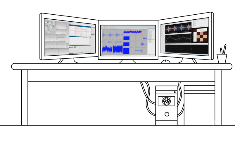
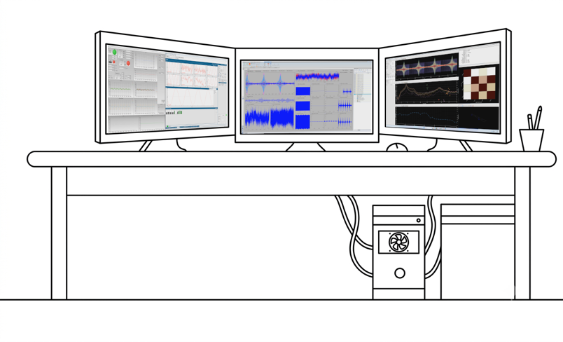
Furthermore, OMA proved to be an essential tool to enable the correct execution of the tests by monitoring the wind tunnel runs along with a combination of other software. In real-life, the monitoring capabilities provided could be employed to enable controller fault detections, isolation and recovery logics. Next to OMA, that was running in the DLR Online Monitoring (OLM) system, the GUI of the real-time controller was employed to change the controller settings remotely from the control room. The final monitoring of the signals delivered and received from the demonstrator were carried out using the a commercial measurement system. The resulting monitoring setup is depicted in Fig.3. This setup enabled real-time monitoring of experimental data and allowed for adjustment of the controller settings as needed.
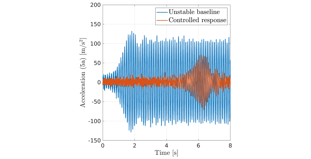
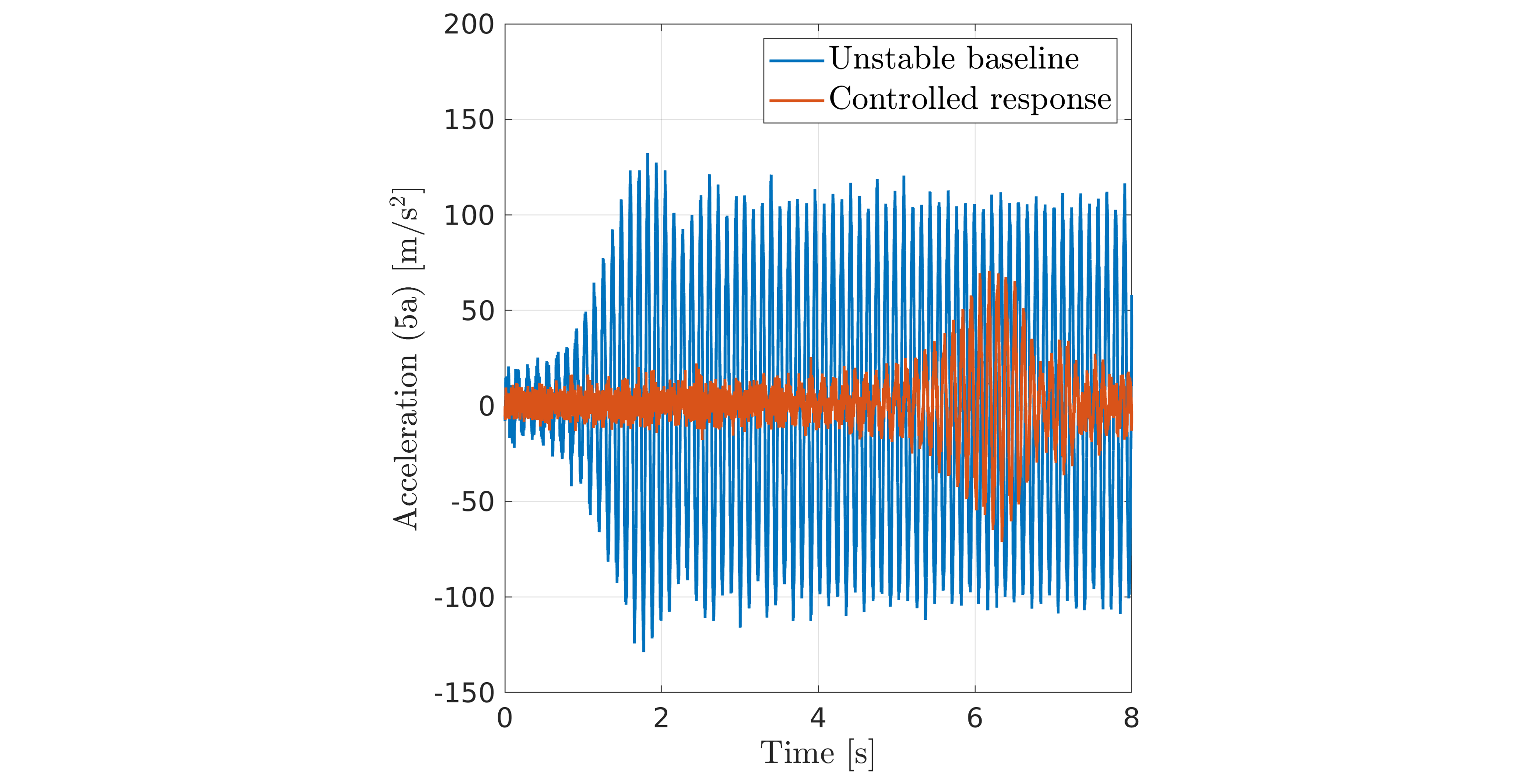
The plot of Fig. 4 displays the acceleration measured by sensor 5a due to a swept-frequency sine excitation with frequency content 2-15 Hz of flap number 1. For the unstable baseline configuration, the wing entered in a LCO due to the presence of the saturation block. However, the initial wing response, prior to saturation of the destabilizing flap, was divergent. This proves that the destabilizing controller successfully provoked the intended instability. In the stabilized configurations, both the numerical models and the experimental data confirm a return to stability. This is clearly reflected in the time-domain response, where vibrations are dramatically suppressed and the LCO present in the unstable baseline is completely eliminated (see Fig. 4). The amplified response between approximately 5 and 7 seconds occurs because the excitation frequency matches the first WB mode during this interval. Despite this increase of the response amplitude, the controlled system remains stable.
Figure 4: Experimental time response due to chirp excitation of Flap 1 at 50 m/s
The final validation: real wind tunnel vs CFD-CSM simulations with controller dynamics
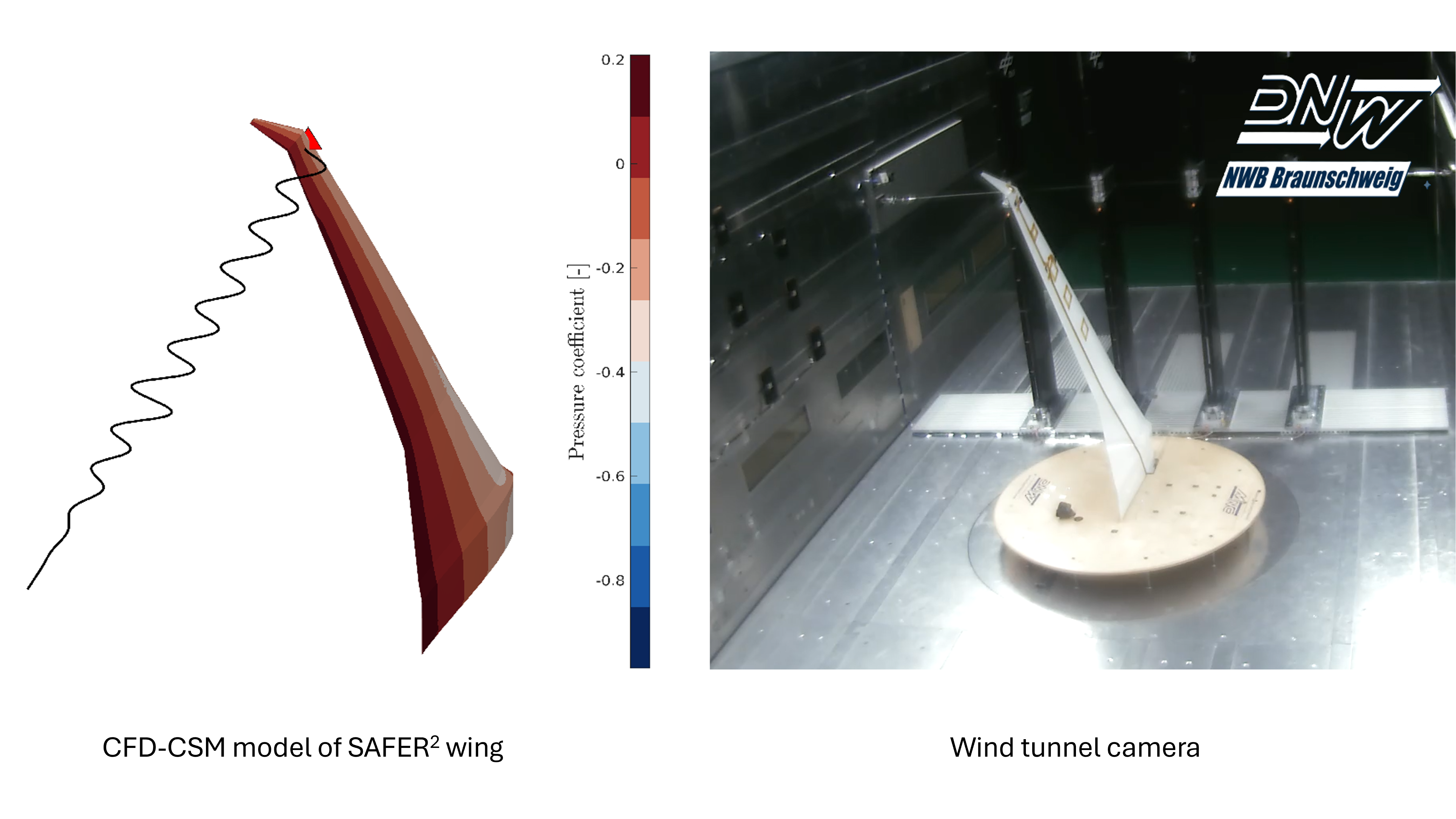
This final stage of the research involved a head-to-head comparison between the experimental data gathered in the DNW-NWB wind tunnel and a high-fidelity numerical workflow. In fact, to ensure that damping augmentation technologies can be safely integrated into future aircraft, it is not enough to simply see them work in a wind tunnel; it must also be proved that mathematical models can accurately predict that behaviour. The simulation environment used for this validation is a sophisticated Computational Fluid Dynamics - Computational Structural Mechanics (CFD-CSM) - Controller framework. The framework solves the equations of motion of the aeroservoelastic system in time domain employing CFD for the computation of the unsteady aerodynamic forces, a finite element model of the structure to account for the wing's flexibility, and it embeds the specific dynamics of the sensors, actuators, and the controllers themselves.
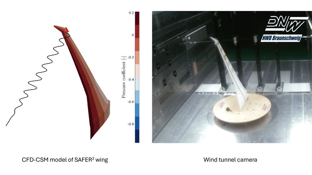
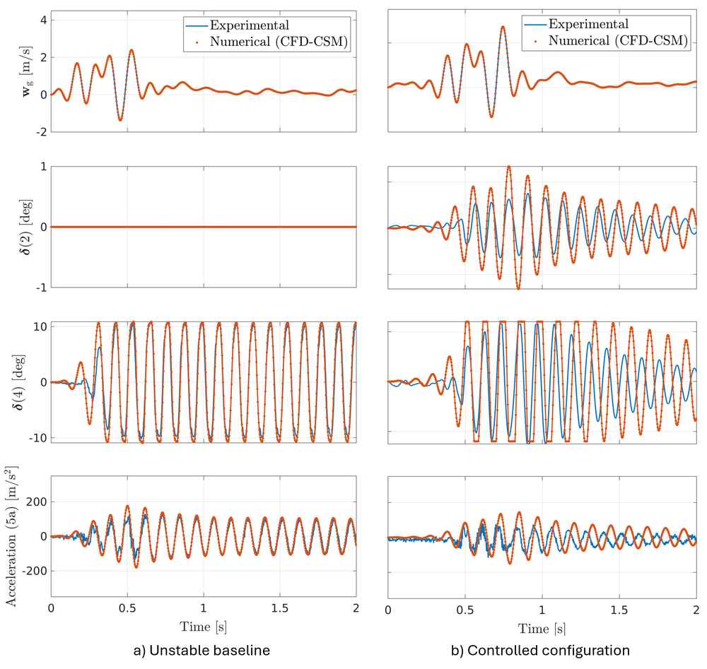
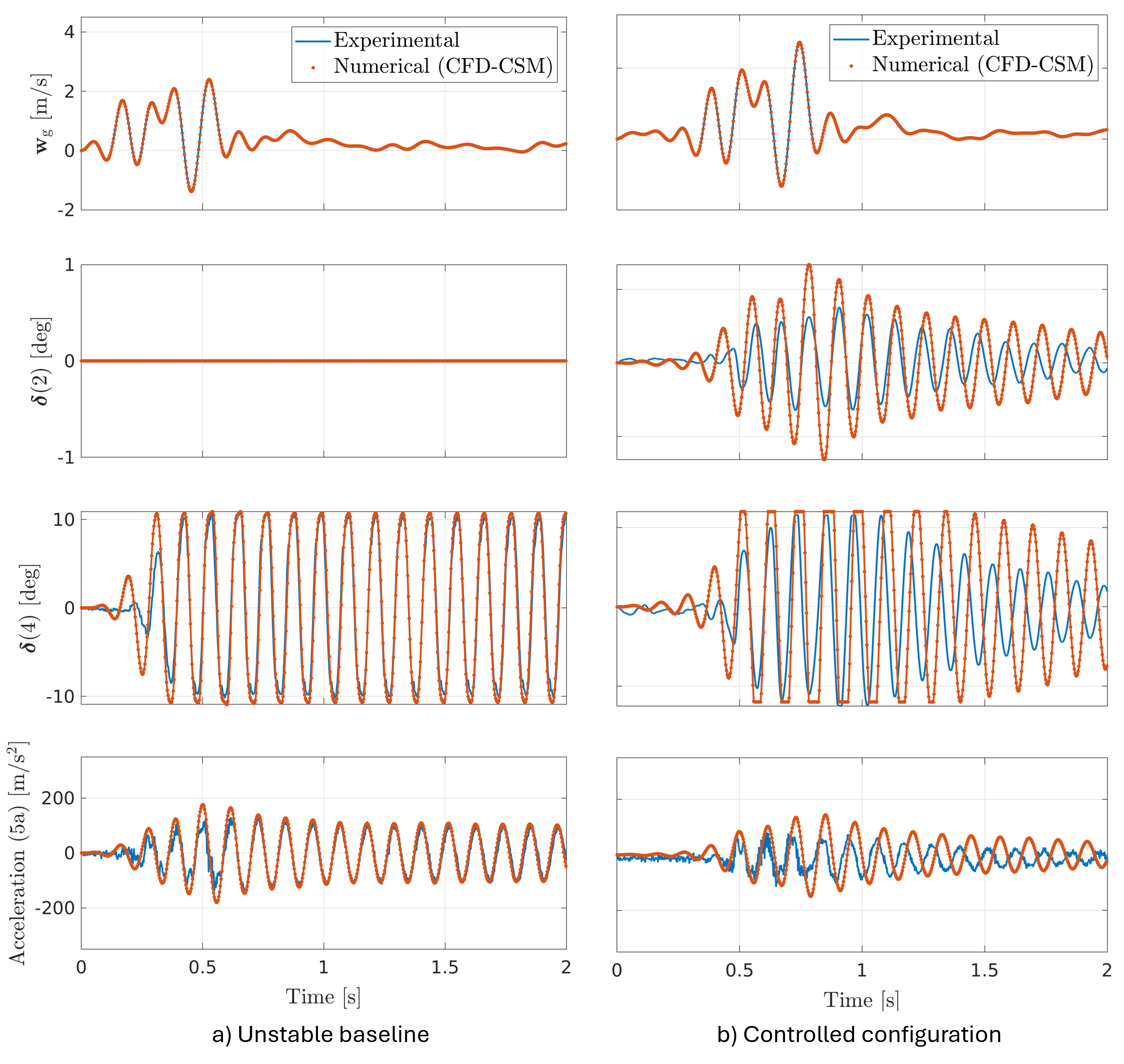
Two simulations are presented: one for the Unstable Baseline and one for the Controlled Response. In both cases the input signal to trigger the motion of the wing is the incremental gust angle resulting from a 360 deg rotation of the gust generator. The gust angle is measured via the 5-hole-probe of the wind tunnel shown in Fig. 1 and it is imposed as an input in the simulation environment. Results are illustrated in Fig. 5 against the experimental measurements. The numerical results are capable of reproducing the unstable and stable behavior of the configuration. For the Unstable Baseline configuration, the simulation also agrees well with the measurements, both in terms of flap deflections and accelerations. Activating the stabilizing controller to the simulation causes the results to diverge from experimental data. This may be attributed to modeling uncertainties of the flaps, both in terms of inertia and generated aerodynamic forces, or even uncertainties in the measurement of the gust signal which make the simulated environment slightly different from the test run. More details can be found in [4].
In conclusion: the developed CFD-CSM-Controller framework proved capable of performing time-accurate aeroservoelastic computations. The results displayed in this article provide a solid foundation for future validation studies.
Figure 5: Experimental versus numerical time response due to a discrete gust encounter at 50 m/s.
[4] Micheli, B., Volkmar, R., Soal, K. I., et al. (2026). Validation of a LFD-Based Workflow for Active Damping Augmentation using Experimental Data. In Proceedings of International Forum on Aeroelasticity and Structural Dynamics 2026 (IFASD), Göttingen, DE
Authors
Boris Micheli, Department Aeroelastic Simulation, DLR Institute ofAeroelasticity
Keith Soal, Department Structural Dynamics and System Identification, DLR Institute of Aeroelasticity