How do modern aircraft engines react to crosswinds?
August 28, 2025 | Test results for fan-inlet interactions
How do modern aircraft engines react to crosswinds?
INFRa-Testrig at the Technical University of Braunschweig
In order to better understand fan inlet interactions, IFAS and the DLR Institute of Propulsion Technology, with support from the DLR Institute of Structures and Design, have jointly developed a fan inlet test rig. The test rig is operated in the IFAS wind tunnel at the Technical University of Braunschweig and simulates part of a modern aircraft engine: the bypass duct, through which a large amount of air is directed around the outside of the engine core.
Credit:
TU Braunschweig, IFAS
Scientists from the German Aerospace Centre, in collaboration with the Technical University of Braunschweig and Leibniz University Hannover, investigated this in a test facility in a wind tunnel, a smaller version of a real engine. They found that the air flow separates depending on the operating point and strength of the crosswind. In addition, the fan blades oscillate due to the different air flow. Crosswinds can therefore reduce the efficiency and service life of the engine.
Modern turbofan engines become more efficient when the bypass ratio is increased. This refers to the air that is diverted around the core engine. However, a higher bypass ratio also increases the diameter of the fan and the inlet. This in turn makes the engine heavier overall. In order to partially offset the additional weight, research is being conducted into how engine inlets can be shortened efficiently. The main challenges are that shorter intakes are less able to homogenise the air flowing into the engine and that the fan operates under disturbed inflow conditions. This means that the fan receives ‘uneven’ air. Here, the close spatial coupling of the components results in increased fan-intake interaction.
Scientists from the German Aerospace Centre, together with the Technical University of Braunschweig and Leibniz University Hannover, investigated this in a test facility in a wind tunnel, a smaller version of a real engine. They found that the air flow separates depending on the operating point and strength of the crosswind. In addition, the fan blades oscillate due to the different air flow. Crosswinds can therefore reduce the efficiency and service life of the engine.
How do modern aircraft engines react to crosswinds?
Your consent to the storage of data ('cookies') is required for the playback of this video on Quickchannel.com. You can view and change your current data storage settings at any time under privacy.
How do modern aircraft engines react to crosswinds?
Scientists from the German Aerospace Centre, together with the Technical University of Braunschweig and Leibniz University Hannover, investigated this in a test facility in a wind tunnel, a smaller version of a real engine. They found that the air flow separates depending on the operating point and strength of the crosswind. In addition, the fan blades oscillate due to the different air flow. Crosswinds can therefore reduce the efficiency and service life of the engine.
Credit:
TU Braunschweig, IFAS
Flow separation and its consequences in crosswinds
Efficient engines must operate optimally at all times and in all operating conditions, i.e. in all phases of flight. However, new designs are not initially configured for all operating conditions. Instead, specific operating conditions that are fundamental to the new design are defined in advance. Based on this design and the data, the operating conditions in other phases of flight are subsequently reviewed. Crosswinds, for example, represent an important operating condition.
Crosswinds occur, for example, in stormy weather when air flows sideways onto the engine. The air is then sucked into the engine from the side. This causes strong acceleration around the inlet lip on the side facing the wind. At high crosswind speeds, the airflow around the inlet lip can lead to flow separation. When flow separation occurs, the air no longer follows the surface. This disturbance can cause various problems:
The fan can generate less thrust.
Vibrations may occur, which can damage the material or components.
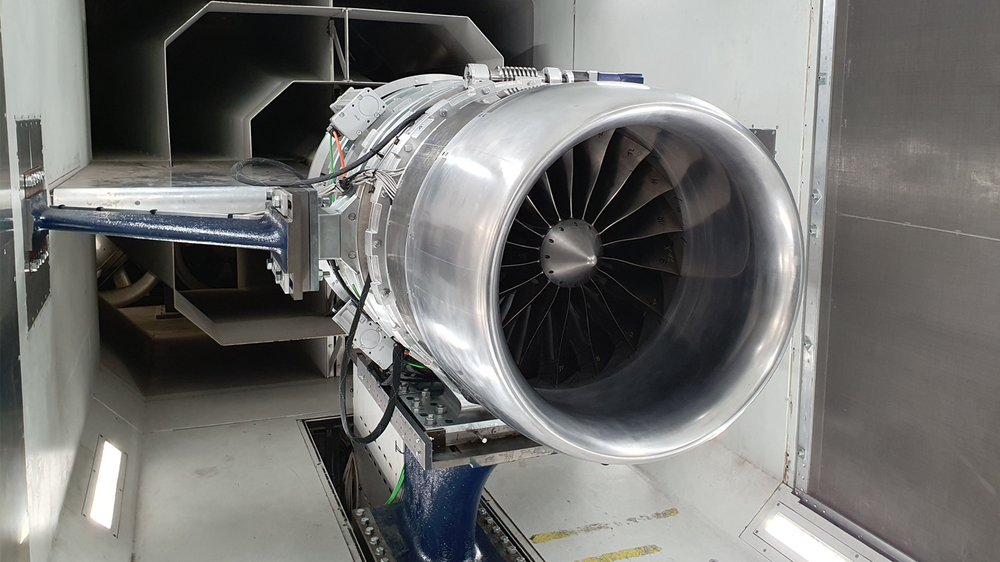
The fan inlet test rig: a scaled-down engine in the wind tunnel
In order to better understand fan inlet interactions, IFAS and the DLR Institute of Propulsion Technology, with support from the DLR Institute of Structures and Design, have jointly developed a fan inlet test rig. The test rig is operated in the IFAS wind tunnel at the Technical University of Braunschweig and simulates part of a modern aircraft engine: the bypass duct, through which a large amount of air is directed around the outside of the engine core. The test facility is about three times smaller than a real engine and simulates an engine with a bypass ratio of 10 to 12. This corresponds to today's efficient aircraft engines. This enables experimental research into fan inlet interactions under realistic operating conditions.
The wind tunnel itself consists of two flow channels that intersect in the test rig area.
The main wind tunnel consists of an open test track and allows flow speeds of Mach 0 to 0.2.
The crosswind tunnel, on the other hand, is a closed test track and allows crosswind speeds of up to 40 knots.
This test setup allows controlled crosswind conditions to be set in the test area, enabling experimental tests to be carried out.
Measurement campaign with crosswind inflow in the wind tunnel
The aerodynamic and aeroelastic interaction of the components in crosswinds was analysed across the entire characteristic range, and crosswind speeds of up to 38 knots were successfully measured.
The research team conducted an initial measurement campaign with crosswind inflow in the wind tunnel. The aerodynamic and aeroelastic interaction of the components in crosswinds was analysed across the entire characteristic map range, and crosswind speeds of up to 38 knots were successfully measured.
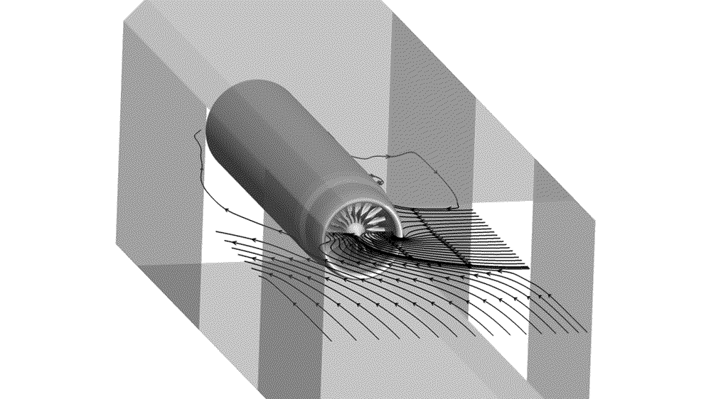
The inlet detaches depending on the crosswind speed and the fan operating point
Your consent to the storage of data ('cookies') is required for the playback of this video on Quickchannel.com. You can view and change your current data storage settings at any time under privacy.
The inlet detaches depending on the crosswind speed and the fan operating point
The inlet detaches depending on the crosswind speed and the fan operating point. The size and intensity of the detachment varied.
As a result, both the fan pressure ratio and the isentropic efficiency decrease.
Compared to a flow-through nacelle, the reattachment point of the separation is shifted upstream due to the interaction with the fan. The fan blade reaches (defined) material limits during resonance runs with crosswinds.
The fan blade also exhibits non-synchronous vibrations excited by the oscillating separation bubble in the inlet.
The experimental data collected during the test campaign will be further evaluated in the future. In addition, there are plans to collect more accurate data on the inflow during follow-up campaigns. This will be done, for example, by using optical measurement technology.