
From Understanding Shock Oscillations to Controlling them
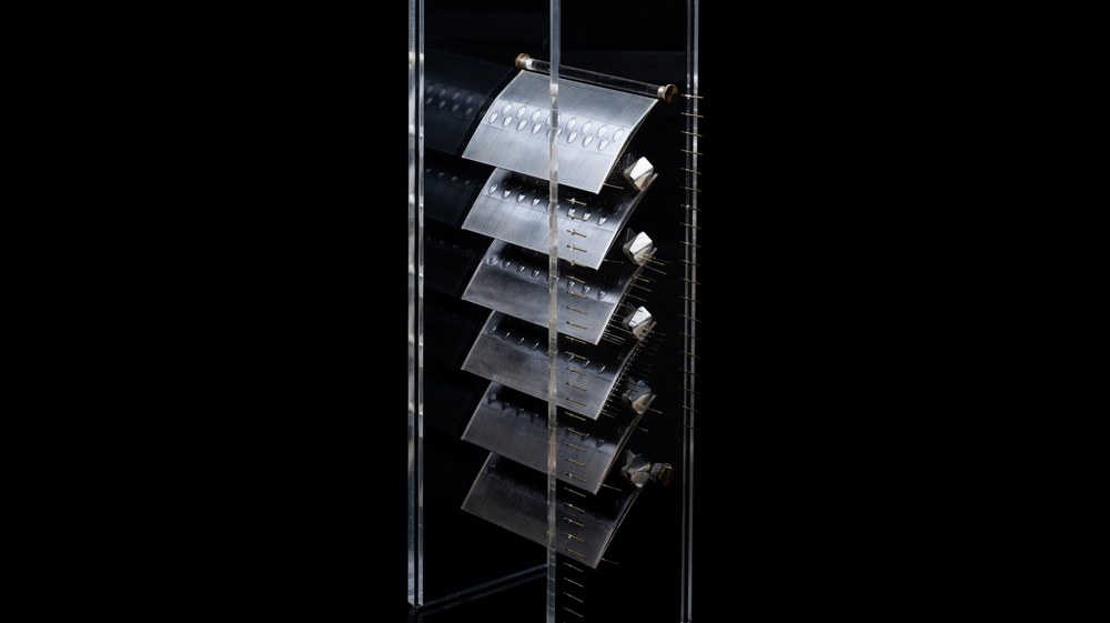

- In transonic fans and compressors shock waves interact with the boundary layer on blade surfaces.
- This shock-boundary layer interaction can negatively affect aerodynamic efficiency and cause potential durability problems.
- In a multi-year research effort, a high-performance transonic compressor cascade was designed and validated experimentally at DLR Cologne.
- This allowed to deeper understand the interactions and finally control them with optimized passive surface features called shock control bumps, significantly advancing transonic compressor aerodynamics.
Shock-Boundary-Layer Interactions
When air flows along the surface of fan and compressor blades, a very thin boundary layer forms due to friction directly on the surface of the blades. Concurrently at transonic and supersonic speeds, shock waves can form in fans and compressors. These shock waves involve a very sudden change in the flow, the local pressure and density increases while the flow is simultaneously decelerated.
When shock waves encounter the boundary layer on the surfaces of the blades they interact and influence each other, essentially altering the flow. This can cause increased aerodynamic losses, unsteady flow separation, and a reduced stable operating range. Beyond reducing efficiency, the interacting shock waves also impose a risk of fluctuating aerodynamic loads on the blade structure that might bring forward durability and fatigue problems, eventually leading to potential fractures of the blades.
Because of these issues, correctly understanding and possibly controlling or reducing the effects is very important in order to design more efficient future aircraft-engine blades. In a multi-year research effort, DLR researchers have analyzed the interactions in detail using unsteady optical measurements and scale resolving simulations and found a way to finally control them, focusing on the blade aerodynamics, with optimized passive surface features. These designed shock control bumps (SCB) significantly reduce aerodynamic losses as well as the shock motion.
The Research Cascade
As a first step towards this achievement, our institute developed the Transonic Cascade TEAMAero as a modern, highly loaded compressor test case. TEAMAero is a research programme funded by the EU under Horizon 2020. For designing the new cascade, our institute combined our AutoOpti optimization environment with the TRACE flow solver.

After successfully designing the new cascade, it was manufactured, instrumented and tested in the Transonic Cascade Wind Tunnel at our site in Cologne at Mach 1.2, in order to prove the numerical design. The test facility is used specifically for investigating compressor blades and flow phenomena in compressors at transonic speeds, close to real operating conditions. Moreover Laser-optic measurement techniques, such as Time-resolved Schlieren imaging and high-speed particle image velocimetry (PIV), allowed the aerodynamic processes to be analysed in detail.
Understanding the shock-oscillation mechanism
The overall cascade losses were predicted within approximately 3-6% over the expected operating range. However, the experiments revealed important flow details that conventional RANS simulations did not reproduce correctly. Particularly interesting was the shock wave oscillation and the unsteady separation bubble beneath the shock.
The measured data at the Transonic Cascade Wind Tunnel showed that the main shock oscillation occurred in a broad frequency range of approximately 500 - 550 Hz. Further, it exposed the mechanism of the shock oscillation cycle that occurs in the cascade, where pressure disturbances generated downstream - partially caused by recirculating flow from the previous cycle - propagate upstream and interact with the main shock.
Additionally, due to a strong oblique shock that propagates upstream from the main shock, the separation bubble under the shock growths during this cycle and causes multiple secondary shocks. This evokes temporary breakdown or choking of the blade passage and strong changes in the local inflow conditions. When the breakdown has occurred a block of detached flow circulates downstream, and a delayed interaction between separated flow structures completes this oscillation cycle, setting it back to its beginning state.
Designing the Shock Control Bumps
This much more detailed physical understanding of the shock-boundary layer interaction enabled the invention of a specifically targeted flow-control concept to influence the shock oscillation. In order to create this concept, a novel automated process chain was developed to generate, mesh, simulate and optimize compressor blades equipped with three-dimensional shock control bumps on the suction side surface. The shock control bumps are passive devices, they required no external energy or active control system since they are built into the aerodynamic structure and design of the compressor blades.
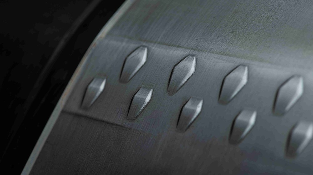
The shock control bumps essentially consist of multiple bumps, that together reduce the effects by the shock-boundary-layer interactions. An upstream bump on the blades gradually pre-compresses the flow before it reaches the main shock. It also generates controlled vortical structures that help the boundary layer remain attached. A downstream bump simultaneously weakens the main shock and promotes flow reattachment. Through this, the bumps create a more favourable lambda-shaped shock structure that anchors the shock system and limits its upstream movement. This does not mean the shock oscillation is completely eliminated, but it is weakened and stabilized.
In order to develop the most optimal design for the shock control bumps, more than 1,300 configurations were evaluated in the process chain, with nearly 900 fully converged numerical solutions. The final selected design uses coordinated pairs of three-dimensional bumps with only 0.4-0.5 mm height on a blade with a 100 mm chord. This optimized configuration was manufactured and tested in the Transonic Cascade wind tunnel. At the aerodynamic design point, the optimized Shock Control Bumps configuration helped achieve about 17% lower total pressure losses, 43% lower deviation of the shock position and an increase in flow turning of about 1.7 deg. The final design thereby proved to be very efficient, even more so than predicted.
While no direct aircraft fuel-burn or engine-level efficiency improvement was yet quantified, the effects on the blade aerodynamics are nonetheless important for more efficient aircraft-engine blading. They also demonstrate how a physics-based combination of numerical optimization and wind-tunnel testing proves to be an efficient way to further develop and optimize fans and compressors.
Related literature:
- Joachim, Klinner, et al. “The Unsteady Shock-Boundary Layer Interaction in a Compressor Cascade - Part I: Measurements With Time-Resolved Particle Image Velocimetry”, Journal of Turbomachinery, 147(9): 091003, 2025, https://doi.org/10.1115/1.4067467.
- Klose, Bjoern F., et al. “The Unsteady Shock–Boundary Layer Interaction in a Compressor Cascade - Part II: High-Fidelity Simulation”, Journal of Turbomachinery, 147(9): 091003, 2025, https://doi.org/10.1115/1.4067097.
- Munoz Lopez, Edwin J., et al. “Novel Methods for the Design of Compressor Blades with Shock Control Bumps”, ASME Turbo Expo, GT2026-177897, 2026, Milan, Italy
- Munoz Lopez, Edwin J., et al. “The Unsteady Shock-Boundary Layer Interaction in a Compressor Cascade - Part III: Mechanisms of Shock Oscillation”, Journal of Turbomachinery, 147(9): 091003, 2025, doi.org/10.1115/1.4066186.