Towards even smoother flights

Jonny CAROLL 2018
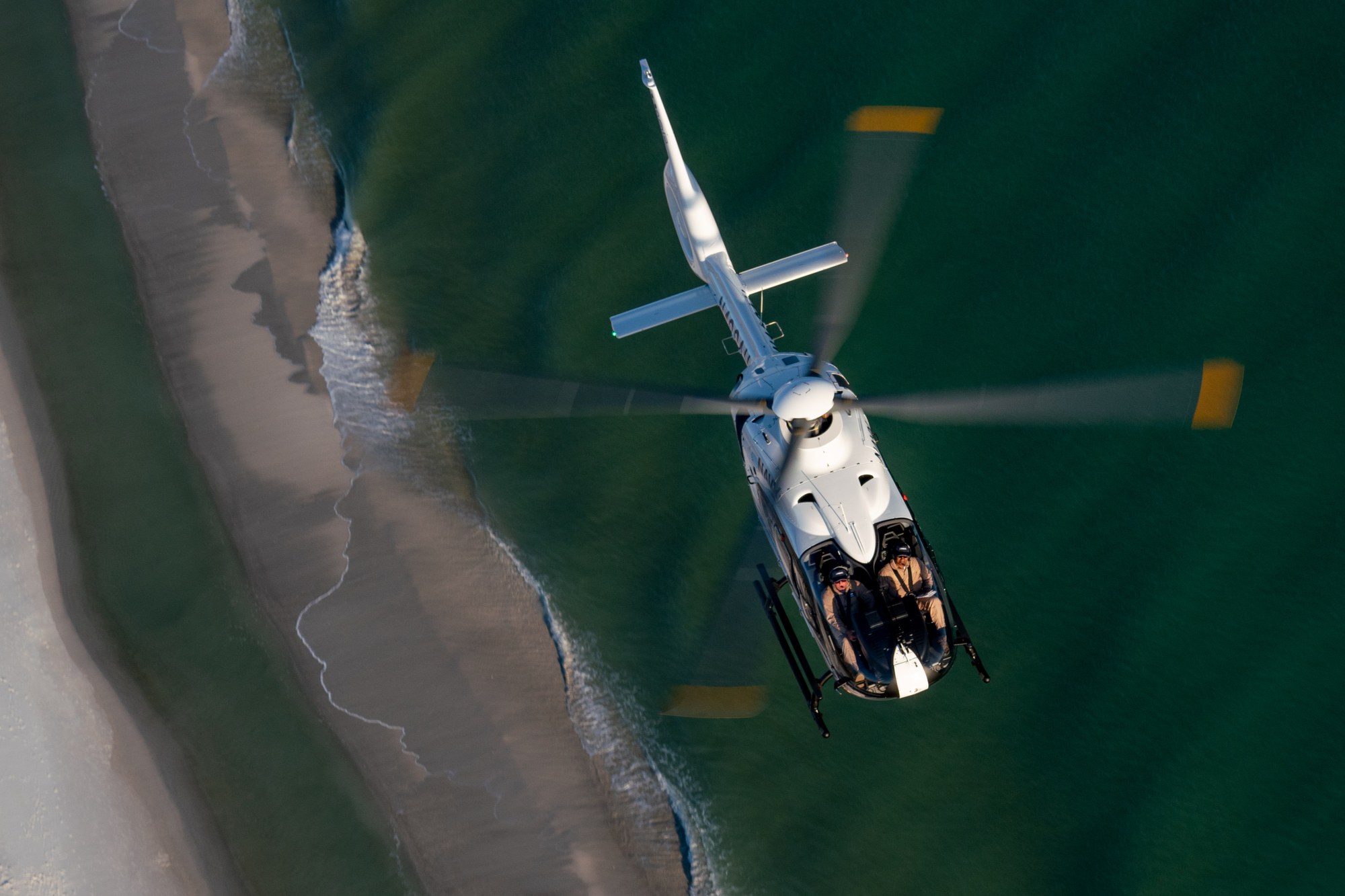
From mountain rescue missions to firefighting and police operations – helicopters are used for a wide variety of purposes. Unlike aeroplanes, they can take off and land vertically. Due to their lightweight construction, helicopters achieve exceptional performance while maintaining low operating costs. However, these versatile aircraft have one drawback – their lightweight structure makes them susceptible to mechanical vibrations, which can render operating the helicopter challenging and, in certain cases, can disrupt missions that, for instance, demand patient transport or aerial reconnaissance using high-resolution cameras. Today, the design process for helicopters relies heavily on computer-based methods. The underlying models employed must be as realistic as possible. In order to achieve this, researchers from the DLR Institute of Aeroelasticity followed the construction of a helicopter, analysing its components, step by step.
Making vibrations visible
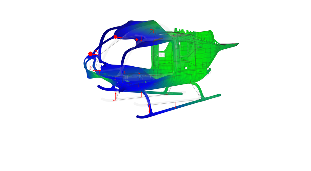
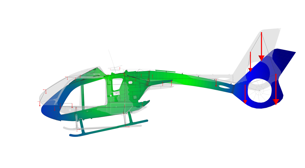
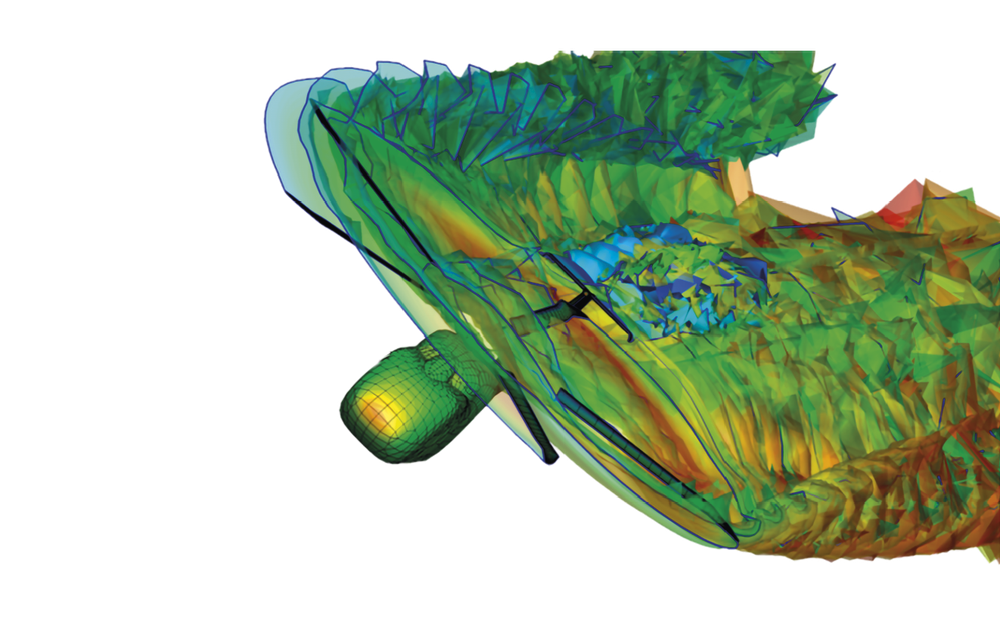
Vibrations occur as a result of dynamic rotor loads, mainly due to the crossflow on the main rotor, and therefore cannot be entirely eliminated. From this source, they propagate throughout the aircraft's entire structure. To create a helicopter that vibrates as little as possible, experts must calculate the forces involved in advance. Today, they use computer-aided methods such as CFD or MBS (see glossary). In the second step, the developers simulate the effect of the vibrations on the helicopter's airframe. The simulation program shows how the forces are transmitted in the airframe and where the vibrations are largest. Based on this simulation, measures are then developed to systematically reduce the vibrations. However, the models on which the calculations are based are not yet sufficiently accurate.
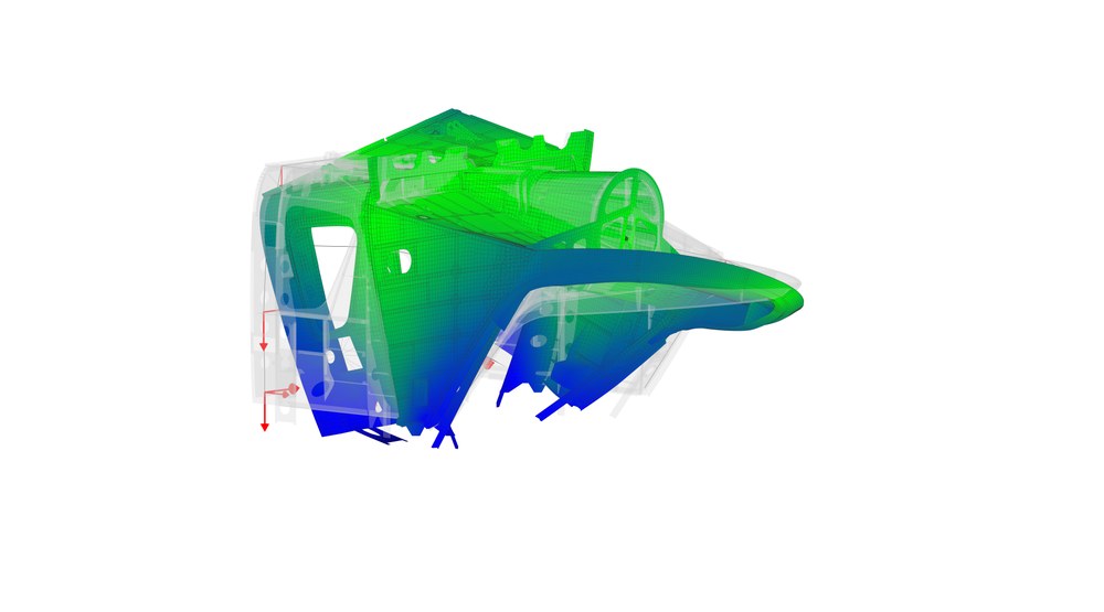
The objective – a model as close to reality as possible
To change this, researchers from the DLR Institute of Aeroelasticity and developers from Airbus Helicopters Germany joined forces in the eVolve project. Their objective was to improve digital helicopter models in such a way that they represent vibrations as realistically as possible. Such computational models are created during the design phase. Researchers use CAD and FEM models (see glossary) and make assumptions about the mechanical behaviour of the structure. At the end of the design phase, they build a prototype. During a shake test, the researchers study the dynamic behaviour of the structure. They compare the test results with the results from the FEM simulation. If the disparities between test and simulation exceed an acceptable threshold, the models must be adjusted to better align with reality. Designing a complete helicopter is highly complex, presenting numerous possible areas where disparities can occur. These are usually due to incorrect assumptions about mechanical behaviour, which are checked and improved through comparisons with the test data.
Glossary
CFD: Computational Fluid Dynamics (CFD) is the realisation of fluid mechanics as a computer program. The underlying physics are herein described by the Navier-Stokes equations, Euler equations and potential equations.
MBS: Multibody simulation (MBS) models the interactions between multiple mechanical components, allowing researchers to compute intricate motion sequences and forecast dynamic responses or the behaviour of moving parts.
CAD: Computer-Aided Design (CAD) utilises software to generate designs, models, structures and technical drawings on a computer, streamlining the process of creating designs or engineering drawings.
FEM: The Finite Element Method (FEM) is a simulation technique often used to solve mechanical problems for complex geometries. The structures are divided into smaller regions, or 'finite elements', for which the corresponding equations are easier to set up.
Airbus Helicopters
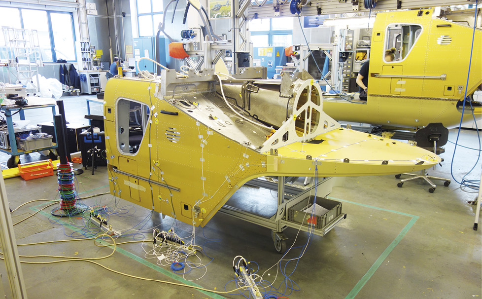
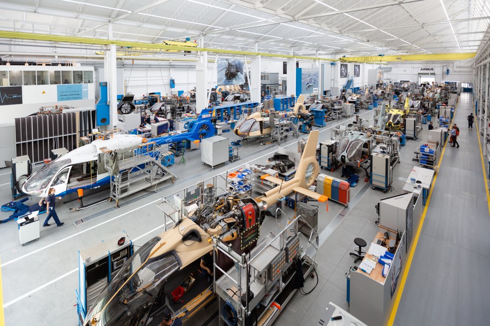
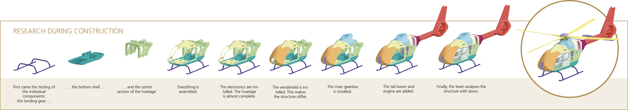
In the eVolve project, the team analysed individual components as they were gradually integrated into a fully assembled helicopter on the production line. This approach enables the early detection of modelling errors within smaller components. However, the component testing did not take place at the DLR laboratory in Göttingen, but in Donauwörth, where Airbus helicopters are manufactured. The initial phase involved selecting a candidate to track throughout the production process. Helicopters are often fitted with customised equipment such as winches, radar systems, cameras and stretchers. To investigate an exemplar, whose dynamic behaviour is as universally valid as possible, they chose a helicopter which was as standard as possible. The selected exemplar had no additional attachments or external structures.

Airbus Helicopters
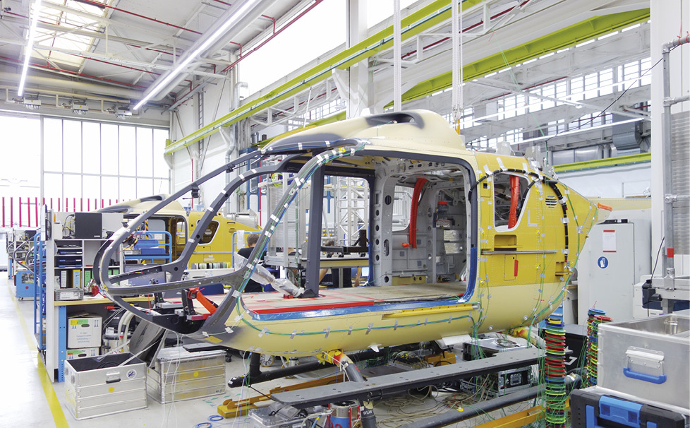
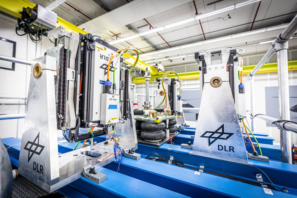
The progress of construction affects the vibration behaviour of a helicopter. At some assembly stations, the mass or stiffness of the overall structure changes significantly. These are therefore particularly relevant for structural dynamics. This is where the DLR team conducted their measurements. "Carrying out experiments in the middle of ongoing production was quite unusual for us. We usually conduct measurements in controlled environments such as hangars or laboratories. This was a little different," explains Johannes Knebusch from the DLR Institute of Aeroelasticity.
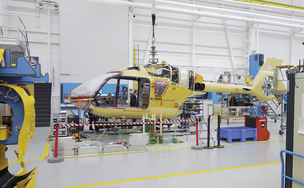
The team had to adapt to new situations at each station. At the first assembly station, the researchers were able to induce forces using an impact hammer due to the limited number of parts. However, towards the end of the process, they had to employ electrodynamic shakers similar to those used for vibration measurements on large aircraft. During the experiments, the helicopter was suspended by bungee cords. These cords ensured consistent boundary conditions, enabling comparable results. "Another factor was that we did not want to hold up the production process with our experiments, which we succeeded in doing. Our partners were exceptionally flexible, greatly facilitating our work," adds Marc Böswald, a head of department at the DLR Institute of Aeroelasticity. Based on the results, the researchers created a dynamic model for each construction stage and compared it with the existing simulation models. This made it possible to see where there were errors in the simulation models. In total, the team carried out measurements at 10 assembly stations. In the first tests, they used only approximately 30 sensors, but at the last station there were more than 200.
The comparison with test data forms the basis for adapting and further improving the existing simulation models. Another advantage is that simulations from early stages show the modes of vibration of individual components. These can be used to pinpoint model errors in various assemblies, which can no longer be detected when the complete helicopter is tested. In future, Airbus plans to apply this method to other helicopter types in order to improve its simulation models – another important step towards the development of low-vibration helicopters.
Airbus Helicopters
Improving future helicopters
The flight behaviour, structural loads, vibrations, passenger comfort and noise of a helicopter are all determined by aeromechanics. While aerodynamics describes the behaviour in relation to air-induced forces such as lift and drag, aeromechanics refers to the interaction between aerodynamics, flight mechanics and structural dynamics. It plays an important role in the development of new helicopter concepts. The eVolve project aims to improve the prediction of aeromechanics. This reduces the development risk and time to market for both classic helicopters and innovative rotorcraft concepts such as air taxis. Under the leadership of Airbus Helicopters Deutschland, DLR is conducting research in the project together with Airbus Defence and Space, the University of Stuttgart and the Technical University of Munich. In eVolve, DLR researchers are developing simulation methods that can be used to better model the aeromechanics of helicopter rotors, they are creating a database that predicts the noise emission from air taxis, and they are developing approaches for predicting and damping vibrations. The DLR institutes of Aerodynamics and Flow Technology, Aeroelasticity and Flight Systems, and the Institute for Software Technology are involved. The project started in September 2021 and will end in August 2024.
An article by Johannes Knebusch and Marc Böswald from the DLRmagazine 174